
Physics for Scientists and Engineers: Foundations and Connections
1st Edition
ISBN: 9781133939146
Author: Katz, Debora M.
Publisher: Cengage Learning
expand_more
expand_more
format_list_bulleted
Videos
Textbook Question
Chapter 29, Problem 46PQ
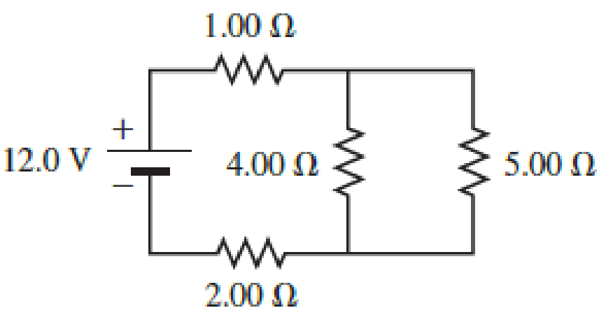
Figure P29.46 shows a circuit with a 12.0-V battery connected to four resistors. How much power is delivered to each resistor?
Expert Solution & Answer

Trending nowThis is a popular solution!

Chapter 29 Solutions
Physics for Scientists and Engineers: Foundations and Connections
Ch. 29.1 - What are the SI units of ?Ch. 29.1 - Prob. 29.2CECh. 29.2 - Prob. 29.3CECh. 29.4 - Prob. 29.5CECh. 29.4 - Prob. 29.6CECh. 29.5 - Prob. 29.7CECh. 29 - Study the symbols in Table 29.2. Then, without...Ch. 29 - Prob. 2PQCh. 29 - Prob. 3PQCh. 29 - Suppose you need to measure the potential...
Ch. 29 - Prob. 5PQCh. 29 - Prob. 6PQCh. 29 - A real battery (modeled as an ideal emf device in...Ch. 29 - Prob. 8PQCh. 29 - Two circuits made up of identical ideal emf...Ch. 29 - Prob. 10PQCh. 29 - Prob. 11PQCh. 29 - Prob. 12PQCh. 29 - Eight real batteries, each with an emf of 5.00 V...Ch. 29 - Prob. 14PQCh. 29 - Prob. 15PQCh. 29 - Prob. 16PQCh. 29 - Prob. 17PQCh. 29 - Prob. 18PQCh. 29 - Prob. 19PQCh. 29 - An ideal emf device with emf is connected to two...Ch. 29 - Prob. 21PQCh. 29 - Prob. 22PQCh. 29 - Prob. 23PQCh. 29 - Prob. 24PQCh. 29 - Prob. 25PQCh. 29 - Prob. 26PQCh. 29 - Determine the currents through the resistors R2,...Ch. 29 - The emf devices in the circuits shown in Figure...Ch. 29 - Prob. 29PQCh. 29 - Prob. 30PQCh. 29 - Prob. 31PQCh. 29 - Prob. 32PQCh. 29 - Prob. 33PQCh. 29 - Prob. 34PQCh. 29 - A Figure P29.35 shows a combination of six...Ch. 29 - A Each resistor shown in Figure P29.36 has...Ch. 29 - Each resistor shown in Figure P29.36 has a...Ch. 29 - Prob. 38PQCh. 29 - Prob. 39PQCh. 29 - The emf in Figure P29.40 is 4.54 V. The...Ch. 29 - Figure P29.41 shows three resistors (R1 = 14.0 ,...Ch. 29 - Figure P29.42 shows five resistors and two...Ch. 29 - The emfs in Figure P29.43 are 1 = 6.00 V and 2 =...Ch. 29 - Prob. 44PQCh. 29 - Figure P29.45 shows five resistors connected...Ch. 29 - Figure P29.46 shows a circuit with a 12.0-V...Ch. 29 - Two ideal emf devices are connected to a set of...Ch. 29 - Two ideal emf devices are connected to a set of...Ch. 29 - Three resistors with resistances R1 = R/2 and R2 =...Ch. 29 - Prob. 51PQCh. 29 - Prob. 52PQCh. 29 - Prob. 53PQCh. 29 - Prob. 55PQCh. 29 - At time t = 0, an RC circuit consists of a 12.0-V...Ch. 29 - A 210.0- resistor and an initially uncharged...Ch. 29 - Prob. 58PQCh. 29 - A real battery with internal resistance 0.500 and...Ch. 29 - Figure P29.60 shows a simple RC circuit with a...Ch. 29 - Prob. 61PQCh. 29 - Prob. 62PQCh. 29 - Prob. 63PQCh. 29 - Ralph has three resistors, R1, R2, and R3,...Ch. 29 - Prob. 65PQCh. 29 - An ideal emf device is connected to a set of...Ch. 29 - Prob. 67PQCh. 29 - An ideal emf device (24.0 V) is connected to a set...Ch. 29 - Prob. 69PQCh. 29 - What is the equivalent resistance between points a...Ch. 29 - A capacitor with initial charge Q0 is connected...Ch. 29 - Prob. 73PQCh. 29 - Prob. 74PQCh. 29 - Prob. 75PQCh. 29 - Prob. 76PQCh. 29 - Figure P29.77 shows a circuit with two batteries...Ch. 29 - In the RC circuit shown in Figure P29.78, an ideal...Ch. 29 - Prob. 79PQCh. 29 - Calculate the equivalent resistance between points...Ch. 29 - In Figure P29.81, N real batteries, each with an...Ch. 29 - Prob. 82PQCh. 29 - Prob. 83PQCh. 29 - Prob. 84PQCh. 29 - Figure P29.84 shows a circuit that consists of two...Ch. 29 - Prob. 86PQCh. 29 - Prob. 87PQCh. 29 - Prob. 88PQCh. 29 - Prob. 89PQCh. 29 - Prob. 90PQCh. 29 - Prob. 91PQCh. 29 - Prob. 92PQCh. 29 - Prob. 93PQCh. 29 - Prob. 94PQCh. 29 - Prob. 95PQ
Knowledge Booster


Learn more about
Need a deep-dive on the concept behind this application? Look no further. Learn more about this topic, physics and related others by exploring similar questions and additional content below.Similar questions
- What is the equivalent resistance between points a and b of the six resistors shown in Figure P29.70? FIGURE P29.70arrow_forwardFigure P29.45 shows five resistors connected between terminals a and b. a. What is the equivalent resistance of this combination of resistors? b. What is the current through each resistor if a 24.0-V battery is connected across the terminals?arrow_forwardConsider the circuit shown in Figure P28.21 on page 860. (a) Find the voltage across the 3.00-0 resistor, (b) Find the current in the 3.00-12 resistor.arrow_forward
- (a) Can the circuit shown in Figure P18.29 be reduced to a single resistor connected to the batteries? Explain. (b) Find the magnitude of the current and its direction in each resistor. Figure P18.29arrow_forwardThree 100- resistors are connected as shown in Figure P21.41 The maximum power that can safely be delivered to any one resistor is 25.0 W. (a) What is the maximum potential difference that can be applied to the terminals a and b? (b) For the voltage determined in part (a), what is the power delivered to each resistor? (c) What is the total power delivered to the combination of resistors?arrow_forwardA Figure P29.35 shows a combination of six resistors with identical resistance R. What is the equivalent resistance between points a and b?arrow_forward
- Calculate the equivalent resistance between points P and Q of the electrical network shown in Figure P29.80.arrow_forwardFigure P29.77 shows a circuit with two batteries and three resistors. a. How much current flows through the 2.00- resistor? b. What is the potential difference between points a and b in the circuit?arrow_forwardA battery is used to charge a capacitor through a resistor as shown in Figure P27.44. Show that half the energy supplied by the battery appears as internal energy in the resistor and half is stored in the capacitor. Figure P27.44arrow_forward
- In Figure P29.81, N real batteries, each with an emf and internal resistance r, are connected in a closed ring. A resistor R can be connected across any two points of this ring, causing there to be n real batteries in one branch and N n resistors in the other branch. Find an expression for the current through the resistor R in this case.arrow_forwardThe circuit shown in Figure P28.78 is set up in the laboratory to measure an unknown capacitance C in series with a resistance R = 10.0 M powered by a battery whose emf is 6.19 V. The data given in the table are the measured voltages across the capacitor as a function of lime, where t = 0 represents the instant at which the switch is thrown to position b. (a) Construct a graph of In (/v) versus I and perform a linear least-squares fit to the data, (b) From the slope of your graph, obtain a value for the time constant of the circuit and a value for the capacitance. v(V) t(s) In (/v) 6.19 0 5.56 4.87 4.93 11.1 4.34 19.4 3.72 30.8 3.09 46.6 2.47 67.3 1.83 102.2arrow_forwardFour resistors are connected to a battery as shown in Figure P21.40. The current in the battery is I, the battery emf is , and the resistor values are R1 = R, R2 = 2R, R3 = 4R, and R4 = 3R. (a) Rank the resistors according to the potential difference across them, from largest to smallest. Note any cases of equal potential differences. (b) Determine the potential difference across each resistor in terms of . (c) Rank the resistors according to the current in them, from largest to smallest. Note any cases of equal currents. (d) Determine the current in each resistor in terms of I. (e) If R3 is increased, what happens to the current in each of the resistors? (f) In the limit that R3 , what are the new values of the current in each resistor in terms of I, the original current in the battery? Figure P21.40arrow_forward
arrow_back_ios
SEE MORE QUESTIONS
arrow_forward_ios
Recommended textbooks for you
 Physics for Scientists and Engineers: Foundations...PhysicsISBN:9781133939146Author:Katz, Debora M.Publisher:Cengage Learning
 College PhysicsPhysicsISBN:9781305952300Author:Raymond A. Serway, Chris VuillePublisher:Cengage Learning
 College PhysicsPhysicsISBN:9781285737027Author:Raymond A. Serway, Chris VuillePublisher:Cengage Learning
 Physics for Scientists and Engineers, Technology ...PhysicsISBN:9781305116399Author:Raymond A. Serway, John W. JewettPublisher:Cengage Learning
 Principles of Physics: A Calculus-Based TextPhysicsISBN:9781133104261Author:Raymond A. Serway, John W. JewettPublisher:Cengage Learning
 Physics for Scientists and Engineers with Modern ...PhysicsISBN:9781337553292Author:Raymond A. Serway, John W. JewettPublisher:Cengage Learning
Physics for Scientists and Engineers: Foundations...
Physics
ISBN:9781133939146
Author:Katz, Debora M.
Publisher:Cengage Learning
College Physics
Physics
ISBN:9781305952300
Author:Raymond A. Serway, Chris Vuille
Publisher:Cengage Learning
College Physics
Physics
ISBN:9781285737027
Author:Raymond A. Serway, Chris Vuille
Publisher:Cengage Learning
Physics for Scientists and Engineers, Technology ...
Physics
ISBN:9781305116399
Author:Raymond A. Serway, John W. Jewett
Publisher:Cengage Learning
Principles of Physics: A Calculus-Based Text
Physics
ISBN:9781133104261
Author:Raymond A. Serway, John W. Jewett
Publisher:Cengage Learning
Physics for Scientists and Engineers with Modern ...
Physics
ISBN:9781337553292
Author:Raymond A. Serway, John W. Jewett
Publisher:Cengage Learning
How To Solve Any Resistors In Series and Parallel Combination Circuit Problems in Physics; Author: The Organic Chemistry Tutor;https://www.youtube.com/watch?v=eFlJy0cPbsY;License: Standard YouTube License, CC-BY