
Physics for Scientists and Engineers: Foundations and Connections
1st Edition
ISBN: 9781133939146
Author: Katz, Debora M.
Publisher: Cengage Learning
expand_more
expand_more
format_list_bulleted
Videos
Textbook Question
Chapter 29, Problem 28PQ
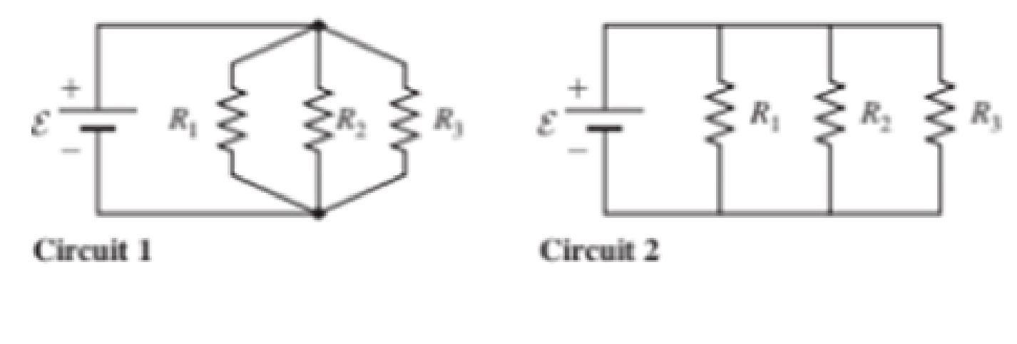
The emf devices in the circuits shown in Figure P29.28 are identical.
- a. Redraw circuit 1 in figure P29.28, including (and labeling) the current in each branch of the circuit. Apply the junction rule to write an equation in terms of the currents you have labeled.
- b. Repeat part (a) for circuit 2 in Figure P29.28.
- c. Simplify your equations if necessary, and compare your answers for each circuit. What can you say about the two circuits?
Expert Solution & Answer
Want to see the full answer?
Check out a sample textbook solution
Students have asked these similar questions
S
3. For the circuit shown to the
right, the resistance is 4,000
Ohms, the capacitance is 100x10-6
F, and the battery is 30 V.
+
C
a. What is the time constant for the circuit?.
b. What is the current in the circuit at t = 0 and t = infinity?
c. What is the current in the circuit as a function of time?
B. A single 100 Q resistor is in series with a 50 V battery. What is the current in
the circuit and the voltage across the resistor?
6. a. Draw a circuit diagram of a resistor hooked up to a battery so current flows through the resistor.
b. For your circuit, indicate where the highest potential is (label with an “H" on the circuit) and where the
lowest potential is (label with an “L" on the circuit.)
c. For your circuit, indicate the direction of the current (conventional current I) with an arrow drawn on the
circuit.
d. Does the current flow from high to low potential, or from low to high potential?
e. What is the direction of the actual electron flow in the circuit? (Describe, don't mark on the circuit.)
Where is the current highest in the circuit? (Describe don't mark on the circuit )
Chapter 29 Solutions
Physics for Scientists and Engineers: Foundations and Connections
Ch. 29.1 - What are the SI units of ?Ch. 29.1 - Prob. 29.2CECh. 29.2 - Prob. 29.3CECh. 29.4 - Prob. 29.5CECh. 29.4 - Prob. 29.6CECh. 29.5 - Prob. 29.7CECh. 29 - Study the symbols in Table 29.2. Then, without...Ch. 29 - Prob. 2PQCh. 29 - Prob. 3PQCh. 29 - Suppose you need to measure the potential...
Ch. 29 - Prob. 5PQCh. 29 - Prob. 6PQCh. 29 - A real battery (modeled as an ideal emf device in...Ch. 29 - Prob. 8PQCh. 29 - Two circuits made up of identical ideal emf...Ch. 29 - Prob. 10PQCh. 29 - Prob. 11PQCh. 29 - Prob. 12PQCh. 29 - Eight real batteries, each with an emf of 5.00 V...Ch. 29 - Prob. 14PQCh. 29 - Prob. 15PQCh. 29 - Prob. 16PQCh. 29 - Prob. 17PQCh. 29 - Prob. 18PQCh. 29 - Prob. 19PQCh. 29 - An ideal emf device with emf is connected to two...Ch. 29 - Prob. 21PQCh. 29 - Prob. 22PQCh. 29 - Prob. 23PQCh. 29 - Prob. 24PQCh. 29 - Prob. 25PQCh. 29 - Prob. 26PQCh. 29 - Determine the currents through the resistors R2,...Ch. 29 - The emf devices in the circuits shown in Figure...Ch. 29 - Prob. 29PQCh. 29 - Prob. 30PQCh. 29 - Prob. 31PQCh. 29 - Prob. 32PQCh. 29 - Prob. 33PQCh. 29 - Prob. 34PQCh. 29 - A Figure P29.35 shows a combination of six...Ch. 29 - A Each resistor shown in Figure P29.36 has...Ch. 29 - Each resistor shown in Figure P29.36 has a...Ch. 29 - Prob. 38PQCh. 29 - Prob. 39PQCh. 29 - The emf in Figure P29.40 is 4.54 V. The...Ch. 29 - Figure P29.41 shows three resistors (R1 = 14.0 ,...Ch. 29 - Figure P29.42 shows five resistors and two...Ch. 29 - The emfs in Figure P29.43 are 1 = 6.00 V and 2 =...Ch. 29 - Prob. 44PQCh. 29 - Figure P29.45 shows five resistors connected...Ch. 29 - Figure P29.46 shows a circuit with a 12.0-V...Ch. 29 - Two ideal emf devices are connected to a set of...Ch. 29 - Two ideal emf devices are connected to a set of...Ch. 29 - Three resistors with resistances R1 = R/2 and R2 =...Ch. 29 - Prob. 51PQCh. 29 - Prob. 52PQCh. 29 - Prob. 53PQCh. 29 - Prob. 55PQCh. 29 - At time t = 0, an RC circuit consists of a 12.0-V...Ch. 29 - A 210.0- resistor and an initially uncharged...Ch. 29 - Prob. 58PQCh. 29 - A real battery with internal resistance 0.500 and...Ch. 29 - Figure P29.60 shows a simple RC circuit with a...Ch. 29 - Prob. 61PQCh. 29 - Prob. 62PQCh. 29 - Prob. 63PQCh. 29 - Ralph has three resistors, R1, R2, and R3,...Ch. 29 - Prob. 65PQCh. 29 - An ideal emf device is connected to a set of...Ch. 29 - Prob. 67PQCh. 29 - An ideal emf device (24.0 V) is connected to a set...Ch. 29 - Prob. 69PQCh. 29 - What is the equivalent resistance between points a...Ch. 29 - A capacitor with initial charge Q0 is connected...Ch. 29 - Prob. 73PQCh. 29 - Prob. 74PQCh. 29 - Prob. 75PQCh. 29 - Prob. 76PQCh. 29 - Figure P29.77 shows a circuit with two batteries...Ch. 29 - In the RC circuit shown in Figure P29.78, an ideal...Ch. 29 - Prob. 79PQCh. 29 - Calculate the equivalent resistance between points...Ch. 29 - In Figure P29.81, N real batteries, each with an...Ch. 29 - Prob. 82PQCh. 29 - Prob. 83PQCh. 29 - Prob. 84PQCh. 29 - Figure P29.84 shows a circuit that consists of two...Ch. 29 - Prob. 86PQCh. 29 - Prob. 87PQCh. 29 - Prob. 88PQCh. 29 - Prob. 89PQCh. 29 - Prob. 90PQCh. 29 - Prob. 91PQCh. 29 - Prob. 92PQCh. 29 - Prob. 93PQCh. 29 - Prob. 94PQCh. 29 - Prob. 95PQ
Knowledge Booster


Learn more about
Need a deep-dive on the concept behind this application? Look no further. Learn more about this topic, physics and related others by exploring similar questions and additional content below.Similar questions
- The circuit in Figure P21.59 has been connected for a long time. (a) What is the potential difference across the capacitor? (b) If the battery is disconnected from the circuit, over what time interval does the capacitor discharge to one-tenth its initial voltage?arrow_forward(a) What is the resistance of a 1.00102 , a 2.50k , and a 4.00k resistor connected in series? (b) In parallel?arrow_forwardA .Figure below is a graph of current versus voltage for three resistance values. Determine and R1, R2 and R3. B. You are measuring the current in a circuit that is operated on a 10 V battery. The ammeter reads 50 mA. Later, you notice that the current has dropped to 30 mA. Eliminating the possibility of a resistance change, you must conclude that the voltage has changed. How much has the voltage of the battery changed, and what is its new value?arrow_forward
- A 15 Ω resistor is connected to the terminals of a 1.5 V battery.a. Draw a graph showing the potential as a function of distance traveled through the circuit, starting from V = 0 V at the negative terminal of the battery.b. What is the current in the circuit?arrow_forwardPart of a circuit is shown.a. What is the current through the 3.0 Ω resistor?b. What is the value of the current I?arrow_forwardM 1 Ω 11 V 3 W Ω 16 V a. Write Kirchhoff's junction rule for all junctions in the circuit. b. Write Kirchhoff's loop rule for all the loops in the circuit. c. Solve the circuit by finding the values of all the currents. 2 Ω mi M In this assignment you will be following the problem solving strategy for Kirchhoff Rules. 1. Reproduce, as neatly as possible, on paper, the circuit shown above. Do not make the circuit too small as you will have to add things to it later. 2. Label all relevant points in this circuit. For your benefit these points are marked with dots in the Figure above and they include: circuits junctions (i.e. places where 3/more wires connect), wire "corners" (i.e. places where a single wire is bent), and locations between two components on a single straight wire. These will help identify loops as well as making it easier to keep track of potential differences. Use lower case letters (a, b, c, ...) for this task. 3. For each junction draw and label the currents coming in…arrow_forward
- Four resistors, R, = 12 0, R2 = 15 N, R3 = series combination of R, and R2 is connected in parallel with the series combination of R3 and R4. The combination is then connected across a 12 V DC power supply. 10 N and R4 80 are connected such that the %3D %3D A. Draw the schematic diagram and label the circuit elements. B. Calculate the equivalent resistance of the circuit. C. Find the total current of the circuit, the voltage across each resistor and the current through each resistor.arrow_forwardIn the circuit shown, R 1= 5Ω, R2 = 6 Ω, R3 = 7 Ω, E1 = 9 V, E2 = 5 V and E3 = 12 V.A. Solve for the currents I1,I2, and I3 using Kirchhoff’s rules.B. What is the potential difference Vaf ?arrow_forwardAn uncharged capacitor and a resistor are connected in series to a battery. If & = 9.00 V, C = 20 μF, and R = 2 Mº. a. Find the time constant of the circuit. b. Find the voltage across the resistor at the moment the switch is closed. c. The maximum charge on the capacitor. d. The voltage across the resistor 20 seconds after the switch is closed. e. The time it takes the capacitor to be 50% charged.arrow_forward
- The load across a 120-V battery consists of a series combination of three resistances R1, R2, and R3. R1 is 210 Ohms, R2 is 350 Ohms, and R3 is 120 Ohms. A. Use the given information to sketch a possible circuit diagram. B. Find the total current through the circuit. C. Find the voltage across R3 D. Find the power dissipated in the R1 resistor.arrow_forwarda. Draw a circuit with a battery and two identical light bulbs (same resistance) in series. Label all circuit elements and the current using the notation from Figures 1 and 2. b. If the battery voltage is 3V and the light bulb resistance is 150, what is the voltage drop across each of the light bulbs? What is the current going through each bulb?arrow_forwardFigure shows two circuits. The two batteries are identical and the four resistors all have exactly the same resistance.a. Is ΔVab larger than, smaller than, or equal to ΔVcd ? Explain.b. Rank in order, from largest to smallest, the currents I1 , I2 , and I3 . Explain.arrow_forward
arrow_back_ios
SEE MORE QUESTIONS
arrow_forward_ios
Recommended textbooks for you
 Principles of Physics: A Calculus-Based TextPhysicsISBN:9781133104261Author:Raymond A. Serway, John W. JewettPublisher:Cengage Learning
 Physics for Scientists and EngineersPhysicsISBN:9781337553278Author:Raymond A. Serway, John W. JewettPublisher:Cengage Learning
 Physics for Scientists and Engineers with Modern ...PhysicsISBN:9781337553292Author:Raymond A. Serway, John W. JewettPublisher:Cengage Learning
Principles of Physics: A Calculus-Based Text
Physics
ISBN:9781133104261
Author:Raymond A. Serway, John W. Jewett
Publisher:Cengage Learning
Physics for Scientists and Engineers
Physics
ISBN:9781337553278
Author:Raymond A. Serway, John W. Jewett
Publisher:Cengage Learning
Physics for Scientists and Engineers with Modern ...
Physics
ISBN:9781337553292
Author:Raymond A. Serway, John W. Jewett
Publisher:Cengage Learning
DC Series circuits explained - The basics working principle; Author: The Engineering Mindset;https://www.youtube.com/watch?v=VV6tZ3Aqfuc;License: Standard YouTube License, CC-BY