
International Edition---engineering Mechanics: Statics, 4th Edition
4th Edition
ISBN: 9781305501607
Author: Andrew Pytel And Jaan Kiusalaas
Publisher: CENGAGE L
expand_more
expand_more
format_list_bulleted
Videos
Textbook Question
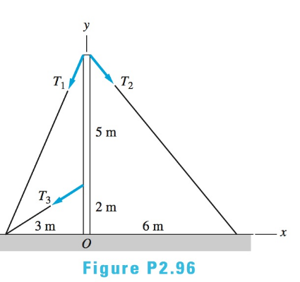
Chapter 2, Problem 2.96RP
The tensions in the cables supporting the pole are
Expert Solution & Answer

Trending nowThis is a popular solution!

Students have asked these similar questions
For the system of forces shown, find the equivalent force-couple system at A. If a
single equivalent force were to act at D, determine the length from B to D. Note that
based on the figure, since there is no given angle for the 150 N force, the manner of
120 N
100 N
60 N
B
1m
270 N-m
150 N
120 N
D
1 m
0.5 m
0.5 m
2 m
which the distance is indicated in the figure suggests that the 150 N force is
perpendicular to the 30° arm of the bar system.
A
30°
Replace the three forces acting on the bent pipe by a single equivalent force R. Specify the distance
d from point O to the point on the x-axis through which the line of action of R passes:
50 lb
40 lb
10
10"
10"
60 lb
The crowbar is subjected to a vertical force of P = 27 lb at the grip, whereas it takes a force of F = 160 lb at the claw to pull the nail out. The crowbar contacts the board at point A.
Find the moment of the force P about point A and the moment of the force F about point A.
Chapter 2 Solutions
International Edition---engineering Mechanics: Statics, 4th Edition
Ch. 2 - Â Which of the force system shown are equivalent...Ch. 2 - Two men are trying to roll the boulder by applying...Ch. 2 - The magnitudes of the three forces applied to the...Ch. 2 - Replace the three forces by a single equivalent...Ch. 2 - Replace the three forces with a single equivalent...Ch. 2 - The forces P1=110lb,P2=200lb, and P3=150lb are...Ch. 2 - Determine the magnitudes of the three forces...Ch. 2 - The magnitudes of the three forces acting on the...Ch. 2 - Determine the three forces acting on the plate...Ch. 2 - The force R is the resultant of the forces P1,P2,...
Ch. 2 - Knowing that the resultant of the two forces is...Ch. 2 - Knowing that the forces P and Q are equivalent to...Ch. 2 - Three ropes support the weight at A. The tension...Ch. 2 - Find the forces Q1,Q2, and Q3 so that the two...Ch. 2 - The man exerts a force P of magnitude 40 1b on the...Ch. 2 - The three forces acting on the beam can be...Ch. 2 - The trapdoor is held in the horizontal plane by...Ch. 2 - Replace the three forces acting on the guy wires...Ch. 2 - The horizontal boom carries the weight W=108lb at...Ch. 2 - The three forces, each of magnitude F, are applied...Ch. 2 - Determine the resultant force R that is equivalent...Ch. 2 - Determine the magnitude and sense of the moment of...Ch. 2 - Find the magnitude and sense of the moment of the...Ch. 2 - Two forces of magnitude P each act on the beam....Ch. 2 - A force P in the xy-plane acts on the triangular...Ch. 2 - A force P in the xy-plane acts on the triangular...Ch. 2 - Determine the moment of the force F=9i+18jlb about...Ch. 2 - Given that T=43kN and W=38kN, determine the...Ch. 2 - A moment of 50lbft about O is required to loosen...Ch. 2 - Determine the moment of the force F about point A...Ch. 2 - The resultant of the two forces shown has a line...Ch. 2 - The tow truck's front wheels will be lifted off...Ch. 2 - The force F acts on the gripper of the robot arm....Ch. 2 - Given that the magnitude of the moment of P about...Ch. 2 - The magnitude of the force P is 160 N. Determine...Ch. 2 - The magnitude of the force Q Determine the moments...Ch. 2 - The magnitude of the moment of force P about point...Ch. 2 - The magnitude of the force P is 50 kN. Determine...Ch. 2 - Determine the combined moment of the two forces...Ch. 2 - Find the combined moment of the forces P and Q...Ch. 2 - The wrench is used to tighten a nut on the wheel....Ch. 2 - The magnitudes of the two forces shown are P=16lb...Ch. 2 - The moment of the force F=50i100j70klb about point...Ch. 2 - Determine the magnitude of the moment of the 150-N...Ch. 2 - The combined moment of the two forces, each of...Ch. 2 - The force F=2i12j+5klb acts along the line AB....Ch. 2 - Calculate the combined moment of the three forces...Ch. 2 - Determine the moment of the force F=40i+30j+20kkN...Ch. 2 - Determine the moment of the 400-lb force about...Ch. 2 - The magnitude of the force F is 55 lb. Calculate...Ch. 2 - The force F=18i12j+10kN is applied to the gripper...Ch. 2 - The legs of the tripod have equal lengths. The...Ch. 2 - Determine the moment of the force F=40i8j+5kN...Ch. 2 - To lift the table without tilting, the combined...Ch. 2 - The combined moment of the three forces is zero...Ch. 2 - The trap door is held open by the rope AB. If the...Ch. 2 - The forces P and Q act on the handles of the...Ch. 2 - The magnitude of the force P is 360 N. Determine...Ch. 2 - The combined moment of P and the 20-lb force about...Ch. 2 - Determine the magnitude of the force F given that...Ch. 2 - The force F of magnitude 200Â NÂ isÂ...Ch. 2 - Calculate the moment of the force P about the axis...Ch. 2 - The force systems in Figs. (a) and (b) have the...Ch. 2 - The force F=F(0.6i+0.8j)kN is applied to the frame...Ch. 2 - Determine the combined moment of the four forces...Ch. 2 - The flexible shaft AB of the wrench is bent into a...Ch. 2 - The magnitude of the force F is 180 lb. Find the...Ch. 2 - Which of the systems are equivalent to the couple...Ch. 2 - Which of the systems are equivalent to the couple...Ch. 2 - If the couple applied to the steering wheel is to...Ch. 2 - Determine the magnitude of the couple shown.Ch. 2 - Determine the couple-vector that is equivalent to...Ch. 2 - Calculate the combined moment of the couple C and...Ch. 2 - Determine the couple-vector that is equivalent to...Ch. 2 - The two forces of magnitude F=30kN form a couple....Ch. 2 - The couple acts on the handles of a steering...Ch. 2 - The force system acting on the plate is equivalent...Ch. 2 - A couple of magnitude 3601b ft is applied about...Ch. 2 - The arm ABCD of the industrial robot lies in a...Ch. 2 - The figure shows one-half of a universal coupling...Ch. 2 - The steering column of the rack-and-pinion...Ch. 2 - Which of the systems are equivalent to the...Ch. 2 - A 15-lb force acts at point A on the high-pressure...Ch. 2 - The bracket, which is fastened to a wall by anchor...Ch. 2 - Replace the three forces applied to the beam by an...Ch. 2 - Replace the two forces shown by a force-couple...Ch. 2 - The figure shows a schematic of a torsion-bar...Ch. 2 - Replace the 250-N force with an equivalent...Ch. 2 - The magnitude of the force F acting at point A on...Ch. 2 - Replace the force-couple system acting on the pipe...Ch. 2 - (a) Replace the force F=2800i+1600j+3000klb acting...Ch. 2 - Determine the force-couple system, with the force...Ch. 2 - Replace the force F and the couple C with an...Ch. 2 - The moment of the force P about the axis AB is...Ch. 2 - Replace the force and the couple shown with an...Ch. 2 - The tensions in the cables supporting the pole are...Ch. 2 - The force acting at A is F=10i+20j5kkN. Knowing...Ch. 2 - The magnitude of the moment of the force P about...Ch. 2 - Calculate the couple-vector formed by the two...Ch. 2 - The magnitudes of the force P and couple C are...Ch. 2 - The resultant force of the three cable tensions...Ch. 2 - The force-couple system shown is equivalent to the...Ch. 2 - Replace the two forces shown with an equivalent...Ch. 2 - The three forces of magnitude P can be replaced by...Ch. 2 - Knowing that the two forces shown can be replaced...Ch. 2 - The trapdoor is held in the position shown by two...Ch. 2 - The force system consists of the force...Ch. 2 - The force system shown can be replaced with a...
Knowledge Booster


Learn more about
Need a deep-dive on the concept behind this application? Look no further. Learn more about this topic, mechanical-engineering and related others by exploring similar questions and additional content below.Similar questions
- 2. Replace the force system acting on the frame by a resultant force (R) and couple moment (MA) at point A. Draw the equivalent force system F=30 kN 2 m 3 m F2=50 kN F= 25 kN 40° 3 m 5 m 30° Aarrow_forwardThe turnbuckle is tightened until the tension in cable AB is 1.1 kN. Calculate the magnitude of the moment about point O of the force acting on point A. 1.4 m 2.3 m 1.3 m 0.9 m Answer: M= kN-marrow_forwardTwo couples act on the structure as shown. Find the magnitude of the resultant couple moment, given: F1 = 170 N, F2 = 180 N, LX = 0.9 m, LY = 1 m, LZ = 0.5 marrow_forward
- The pipe assembly is subjected to three forces of F1 = {3.00, 4.00, -2.00} kip, F2 = {0, 0,-4.00} kip, and F3 = {-3.00, 0, 0} kip. Determine the sum of the moment of the forces 1) about x-axis (the unit vector of x is i) and 2) about line AC. Express the result as a Cartesian vector.arrow_forward4. The wrench is subjected to the 200-N force and the force P as shown. If the equivalent of the two forces is a force R at O and a couple expressed as the vector M = 20k N m, determine the vector expressions for P and R. 300 mm 200 N 160 mm Ans. P = 40j N R = -160j Narrow_forwardDetermine the moment of the three forces about the point A. F = 30 lb F = 20 lb/ 30% 70° 50 lb < 60° 4 in. 1 in. -3.5 in:-arrow_forward
- Calculate the magnitude of the moment about the base point O of the 600-N force. 2 m 40° 600 N 4 marrow_forwardResolve the 360-N force into components along the cables AB and AC. Use α = 55° and β= 30°.arrow_forwardReplace the two forces with an equivalent resultant force and couple moment at point O. Let F = 20 lb.arrow_forward
- Find the magnitude and direction of the resultant for system of forces shown in the figure. Take F1= 35 kN, F2 = 45 kN, F3 =30 kN, F4 = 55 kN, 0, = 40° and 02 = 25° F1 F2 e2 F3 F4arrow_forward10 N at 120°, and C = 16 N at 205° Three coplanar forces are given as follows: A = 6 N at 250°, B = Plot the forces in one Argand plane and label properly. Determine the resultant D, where D = A +2(B - C), expressed in both Polar and Cartesian forms.arrow_forwardReplace the three forces shown by an equivalent force-couple system at point A. If the forces are replaced by a single resultant force, determine the distance d below point A to its line of action. Answers: R= i M= i 160 N 290 N d = Single resultant force. i www Force-couple system at A. The force is positive if to the right, and the couple is positive if counterclockwise. 300 N 650 mm 650 mm 650 mm N N.m mmarrow_forward
arrow_back_ios
SEE MORE QUESTIONS
arrow_forward_ios
Recommended textbooks for you
 International Edition---engineering Mechanics: St...Mechanical EngineeringISBN:9781305501607Author:Andrew Pytel And Jaan KiusalaasPublisher:CENGAGE L
International Edition---engineering Mechanics: St...
Mechanical Engineering
ISBN:9781305501607
Author:Andrew Pytel And Jaan Kiusalaas
Publisher:CENGAGE L
How to balance a see saw using moments example problem; Author: Engineer4Free;https://www.youtube.com/watch?v=d7tX37j-iHU;License: Standard Youtube License