
Concept explainers
Videos
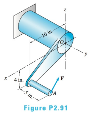
(a) Replace the force
(i)
The equivalent force couple vector acting at O.
Answer to Problem 2.91P
Explanation of Solution
Given Information:
F=-2800i+1600j+3000k
Concept used:
Conclusion:
(ii)
The resolved components of force R into normal component P and the shear component V.
Answer to Problem 2.91P
The normal component is 1600 lb.
The shear component is 4100 lb.
Explanation of Solution
Given:
F=-2800i+1600j+3000k
Concept Used:
Calculation:
Conclusion:
The normal component is 1600 lb.
The shear component is 4100 lb.
(iii)
The resolved components of Resultant couple CR into Torque component T and the bending moment component M.
Answer to Problem 2.91P
The torque component is 18800 lb-in.
The bending moment component is 36900 lb-in
Explanation of Solution
Given:
F=-2800i+1600j+3000k
Concept Used:
Calculation:
Conclusion:
The torque component is 18800 lb-in.
The bending moment component is 36900 lb-in.
Want to see more full solutions like this?
Chapter 2 Solutions
International Edition---engineering Mechanics: Statics, 4th Edition


- Two shafts of a gearbox are subjected to the torques as given in the figure. Replace these couples with a single equivalent couple, specifying its magnitude and direction of its axis. M2=38 lb-ft M1=18 lb-ftarrow_forward- Two different ropes connected to the A ring, FB and FC as in the figure. pulling forces are applied. (ring A is in the x-y plane and its z coordinate is zA =0.) Accordingly, a-) Express the FB force as vector. b-) Vectorial moment of FC force with respect to point B Calculate as. FB=(26)kN, FC = (12)kN, hB = (7)m, hC=(8)marrow_forward4. A Flange has point O as its origin (0,0,0). Calculate the moment about point O of the force vector F1 = -60 i +40 j+20 k lb which has it's point of application located at r1=0i+5j+0kft from point O. Use the cross product rule M=rxF. Calculate the moment of the force vector F2 = 80 i +40 j-30k lb which has it's point of application at r2=4i+5j-2k ft from point O. Add these two moment vectors to find the resultant moment they create about flange's origin O. Answer in vector form. Now determine the value of this resultant moment about the x axis using the dot product rule.arrow_forward
- The Cartesian vector form of the moment produced by force F1 about point O is equal to. 1 ft -2 ft- 3 ft F1 = (-20i + 10j + 30k} lb 2 ft F2 = {-10i – 30j + 50k} lb PA Select one: a. 110i – 50j + 70k Ib.ft b. 110i - 50j + 90k Ib.ft c. 100i + 50j - 80k Ib.ft O d. 110i – 60j - 90k Ib.ftarrow_forward2. Given the cantilever framework below, find the shortest distance from point B to line AC and to line AD. 8' A 3. In the system shown below, determine the length of the common perpendicular between lines AE and BD. Solve in two ways. W = 2200 Ib 4. If the magnitude of a force P acting from A to D is P = 20V73 Ib, determine the component of P that is perpendicular to the plane defined by points E, A, and C. 10' Barrow_forwardVersion: b Determine the length b of the triangular load and its position a on the beam such that the equivalent resultant force is zero and the resultant couple moment is MR Let M₂ = -30 kN - m R Assume the intensities of the distributed loading be w = 12 kN/m w = 5 kN/m r Let the length of the beam be d = 8 m A b W₁ Wr d Note that the sign of MR indicates whether the couple moment is positive (CCW) or negative (CW). Also, position a may be negative, which indicates that the length of the rectangular load is shorter than the triangular load.arrow_forward
- Compute the combined moment of the two 75-lb forces about (a) point O and (b) point A. The moment is positive if counterclockwise, negative if clockwise. Assume a = 7.2 in., b = 3.4 in., F = 75 lb. Answers: (a) Mo= (b) MA= i y lb-in. lb-in.arrow_forwardM. = M-400x 0.15cos30-320 x 0.3= 0 M = 148 Nm CCW mm N 00 Example : Replace the three forces acting on the bent beam by a single equivalent force R. Specify the distance x from the point O in which the line of action of R passes. N 007 160 N 250 mm 250 mm 250 mm 125 mm 240 Narrow_forwardQuestion 2) Forces of F1=7 kN in the +y direction and F2=13 kN in the -z direction are acting on the arm from point B in the figure. From the point C, a moment of magnitude M=4 kN.m acts in the +y direction. The lengths of the arm are also given as L1=0.8 m and L2=0.6 m. The radius r in the a-a section taken over the arm is r=0.023 m and it is desired to determine the stress state at point A. The shear modulus of the sleeve material is G=78 Gpa. According to this;Question 2-A) Find the shear stress at point A due to the shear force. (Write your result in MPa.)Question 2-B) Find the shear stress due to the torsional moment at point A. (Write your result in MPa.)Question 2-C) Find the normal stress caused by the normal force at point A. (Write your result in MPa.)arrow_forward
- Question 2) Forces of F1=7 kN in the +y direction and F2=13 kN in the -z direction are acting on the arm from point B in the figure. From the point C, a moment of magnitude M=4 kN.m acts in the +y direction. The lengths of the arm are also given as L1=0.8 m and L2=0.6 m. The radius r in the a-a section taken over the arm is r=0.023 m and it is desired to determine the stress state at point A. The shear modulus of the sleeve material is G=78 Gpa. According to this;Question 2-D) Find the normal stress that occurs at point A due to the bending moment (formed by the F1 force). (Write your result in MPa.)Question 2-E) Find the amount of torsion (angle) that occurs at point A due to the torque created by the forces. (Write your result in degrees.)arrow_forwardA solid cylindrical shaft anchored to the wall at point O is subjected to 70 N and 85 N couples and a concentrated moment at point E. Determine the resultant couple moment. Hint: You can do this in either of two ways by applying (1) a "scalar" approach by evaluating the individual moments of the x, y, and z components of the 70N and 85N forces, taking positive moments to be in the positive coordinate directions according to the right-hand rule., or (2) the "vector approach" utilizing 3D position vectors using the general cross product definition for the force moment. 70 N 0.8 m 1.2 m 2 6 70 N 1.2 m 0.8 m 9 85 N 12 9 12 -1.2m 1.5m 8 D 85 N C 8 E 200 N·m Xarrow_forward4:48 68 O E B18 Statics_Moment.. o 240 N 2. A prybar is used to remove a nail as 15° shown. Determine 350 mm the moment of the 240 N force about the point o of 65° contact between the prybar and the small support block. 30 mm PROBLEMS 240cos10=236.35 N Mo=? 240 N 15° 65 240sin 10=41.68 N 350 mm M=236.35(0.35) +41.68(0.03)=83.97 N -m 65 (clockwise direction) 30 mm PROBLEMS 900 mm 700 mm 3. An experimental device imparts a force of magnitude F = 225 N to the front edge of the rim at A to simulate the F 300 mm effect of a slam dunk. Determine the moments of the force F about point O and about point B. Finally, locate, 3050 mmarrow_forward
 International Edition---engineering Mechanics: St...Mechanical EngineeringISBN:9781305501607Author:Andrew Pytel And Jaan KiusalaasPublisher:CENGAGE L