
Concept explainers
Videos
a.
The expression for the switching point and the crossover voltages.
a.
Answer to Problem 15.50P
The switching voltage
The lower crossover voltage of Schmitt trigger is
The upper crossover voltage of Schmitt trigger is
Explanation of Solution
Given:
The circuit is given as:
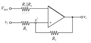
For the ideal operational amplifier, the currents in the inverting and the non-inverting terminal will be zero. By the virtual ground concept the inverting and the non-inverting node voltages will be equal.
Redrawing the circuit:
Applying nodal analysis at inverting node:
Applying nodal analysis at the non-inverting node:
Considering the
Hence, the switching voltage
Evaluating the upper crossover voltage of Schmitt trigger:
Hence, the upper crossover voltage of Schmitt trigger is
Evaluating the lower crossover voltage of Schmitt trigger:
Hence, the lower crossover voltage of Schmitt trigger is
b.
The R1 and VREF for the given condition.
b.
Answer to Problem 15.50P
The reference voltage is
Explanation of Solution
Given:
The circuit is given as:

The crossover voltages are
Substituting the
Hence,
Substitute,
Substitute
Hence,
Substituting,
Therefore, the reference voltage is
Substituting,
Hence, the reference voltage is
Want to see more full solutions like this?
Chapter 15 Solutions
Microelectronics: Circuit Analysis and Design


- A boost regulator has L=0.15 mH and C=0.11 mF with a duty cycle of 0.66 at a switching frequency of 50 kHz. The average load current is la=0.5A. The maximum ripple output voltage is: Select one: a. None of these b. 1.6V C. 2.6V d. 0.6Varrow_forwardt' 3. Predict the input signal frequencies fi and f2 for the block shown in Figure A3. A₁ sin(2af₁t) A₂ Sin (27f₂t) Figure A3 [M [R Output equation: A/2 [cos (18840t)-cos (43960t)]arrow_forwardkindly explain this part ,, how sinc100t is represemted in frequency domainarrow_forward
- EXERCISE PROBLEM Ex 15.1: Design a two-pole low-pass Butterworth filter with a bandwidth of 25 kHz. The largest capacitor value to be used is 50 pF. (Ans. Set C; – 50 pF, then C4 25 pF, R = 180 k2)arrow_forwardactive band pass filter Why does the graphic appear like this in this case discuss it?arrow_forwardExplain the difference between active filters and passive filters in the context of electronic filter design.arrow_forward
- Draw The modulation and demodulation block diagrams of Amplit de Modulation -Vestigial side band (AM-VSB)arrow_forwardExplain how the Active Low Pass Filter works in detail, as shown in a drawingarrow_forwardPhase modulation (PM) can be: O a. Only narrowband. O b. Only wideband. O c. Narrowband or wideband O d. Nothing here. Checkarrow_forward
- FM modulated signal is demodulated using: Select one: O a. Costas PLL O b. Carrier reinsertion method Oc Discriminator followed by integrator O d. Discriminator A Phase-locked loop can be used as: a. FM modulator O b. AM demodulator O c. AM modulator d. FM demodulatorarrow_forwardQ5. Consider the circuit shown. (a) Construct a transition table and state graph for the following circuit. Is the circuit a Mealy or Moore circuit? Does the circuit have any unused states? Assume 00 is the initial state. (b) Draw a timing diagram for the input sequence X= 01100. (c) What is the output sequence for the input sequencſ Q- Do CIk Ck FF Do OCk FFarrow_forwarda. Reduce the following block diagram into a single functional block and determine transfer function C(s)/R(s).b. Determine the range of K for stability for the system shown in the figure.arrow_forward
 Introductory Circuit Analysis (13th Edition)Electrical EngineeringISBN:9780133923605Author:Robert L. BoylestadPublisher:PEARSON
 Delmar's Standard Textbook Of ElectricityElectrical EngineeringISBN:9781337900348Author:Stephen L. HermanPublisher:Cengage Learning
 Programmable Logic ControllersElectrical EngineeringISBN:9780073373843Author:Frank D. PetruzellaPublisher:McGraw-Hill Education
 Fundamentals of Electric CircuitsElectrical EngineeringISBN:9780078028229Author:Charles K Alexander, Matthew SadikuPublisher:McGraw-Hill Education
 Electric Circuits. (11th Edition)Electrical EngineeringISBN:9780134746968Author:James W. Nilsson, Susan RiedelPublisher:PEARSON
 Engineering ElectromagneticsElectrical EngineeringISBN:9780078028151Author:Hayt, William H. (william Hart), Jr, BUCK, John A.Publisher:Mcgraw-hill Education,