
Concept explainers
Videos
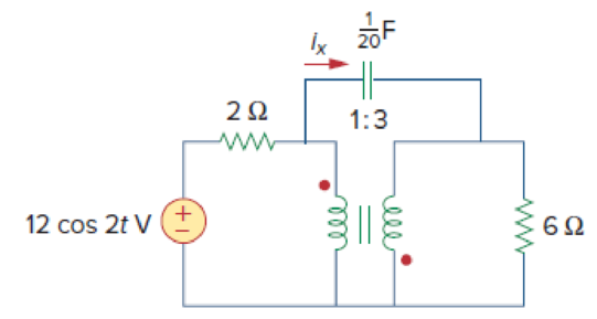
Find current ix in the ideal transformer circuit shown in Fig. 13.114.
Calculate the current
Answer to Problem 49P
The value of current
Explanation of Solution
Given data:
Refer to Figure 13.114 in the textbook for the ideal transformer circuit.
From Figure 13.114, the value of
Calculation:
Consider the expression for the capacitive reactance.
Substitute
Modify the Figure 13.114 by transforming the time-domain circuit with coupled-coils to frequency domain of the circuit with coupled-coil. The frequency domain equivalent circuit is shown in Figure 1.
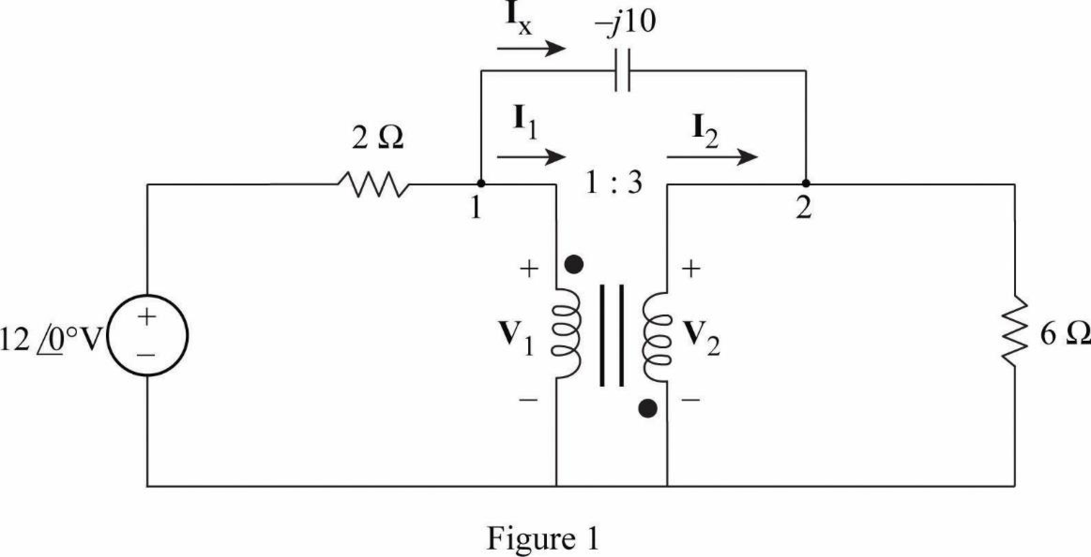
Apply Kirchhoff's current law at node 1 in Figure 1.
Multiply by 2 on both sides of the Equation.
Apply Kirchhoff's current law at node 2 in Figure 1.
Multiply by 6 on both sides of the Equation.
Consider the expression for the turns ratio or transformation ratio.
Substitute
Consider the expression for the turns ratio or transformation ratio.
Substitute
Write equations (1), (2), (3), and (4) in matrix form as follows.
Write the MATLAB code to solve the equation (5).
A = [2 0 (1+j*0.2) (j*(-0.2)); 0 6 (j*0.6) (-1-j*0.6); 0 0 3 1; 1 3 0 0];
B = [12;0;0;0];
C = inv(A)*B
The output in command window:
C =
4.5000 + 0.0000i
-1.5000 + 0.0000i
1.8293 - 1.4634i
-5.4878 + 4.3902i
From the MATLAB output, the values of
Write the expression for the current
Substitute
Substitute
Convert the polar form to time-domain form.
Conclusion:
Thus, the value of current
Want to see more full solutions like this?
Chapter 13 Solutions
Fundamentals of Electric Circuits
Additional Engineering Textbook Solutions
Programmable Logic Controllers
Fundamentals of Applied Electromagnetics (7th Edition)
Electronics Fundamentals: Circuits, Devices & Applications
Principles Of Electric Circuits
Electric Circuits. (11th Edition)
Electric Motors and Control Systems


- 13. A transformer has a turns ratio of 5. If a 100-S resistor is connected across the secondary, what is its resistance referred to the primary? A. 500 2 C. 1000 N D.2500 2 B. 20 2arrow_forward7. The no-load current of a transformer is 4A at 0.25 pf when supplied at 25V, 60Hz. Find the magnetizing component of the no-load currentarrow_forwardThe secondary side of a transformer of 5 primary turns and 9 secondary turns is connected to a resistor of 2 kW. What is the input impedance referred to the primary? Give your answer in kW.arrow_forward
- A 5KVA ideal transformer supplied with 120V RMS and connected to a 1kQ load draws 2A RMS of current on the secondary. What load must be connected in order to draw full power? 1kQ 2.5kQ 8000 3.50arrow_forwardA 10 KVA, 400 / 200 V single phase transformer with resistance 4 percent and reactance 6 percent supplies a current of 50 A a resistive load. Voltage across the load is:arrow_forwardA 24kVA, 6000/200 V transformer during the short circuit test the following result is obtained in the h.v. side: 200W, 4A, 100V. If the low voltage side is 200V at full-load and 0.8 p.f. lag what is the applied voltage at the high voltage sidearrow_forward
- A 24kVA, 6000/200 V transformer during the short circuit test the following result is obtained in the h.v. side: 200W, 4A, 100V. If the low voltage side is 200V at full-load and 0.8 p.f.lag what is the applied voltage at the high voltage sidearrow_forwardA power transformer with a voltage rating of 12500:240 V has a primary current rating of50 A. Find the transformer kVA rating and the secondary current rating if the 240 V is thesecondary voltage rating.arrow_forwardIn the circuit shown in the figure below, if the primary coil has the number of turns of 18, then the number of turns in the secondary coil required, such that maximum power will be delivered to the load of 50 is. 45 0 ww Ideal Transformer ww 00000,arrow_forward
- The input impedance of an ac network can be measured with an ohmmeter. a.False b.True c.True if the ohmmeter is digital d.Sometimesarrow_forwardIn a facility for transformer testing and parameter evaluation, you have been hired as an Electrical Engineer. A step-down transformer with a turn ratio of 10 whose primary is connected to 2200 V has an apparent power rating of 20 KVA. A technician performed the open and closed circuit tests and provided you with the following data. O.C Test (Performed on LV Side): 220 V, 4.2 A, 148 W S.C Test (Performed on HV Side): 86 V, 10.5 A, 360 W You have two major tasks to perform: a) Estimate the parameter of the corresponding equivalent circuit for this transformer with reference to low voltage side b) Also, when this transformer is working at a fully loaded condition with 0.8 PF lagging, calculate the voltage regulation.arrow_forwardThe primary and secondary voltages of an auto-transformer are 500 V and 400 V respectively. Show with the aid of diagram, the current distribution in the winding when the secondary current is 100 A and calculate the economy of Cu in this particular case.arrow_forward
 Introductory Circuit Analysis (13th Edition)Electrical EngineeringISBN:9780133923605Author:Robert L. BoylestadPublisher:PEARSON
 Delmar's Standard Textbook Of ElectricityElectrical EngineeringISBN:9781337900348Author:Stephen L. HermanPublisher:Cengage Learning
 Programmable Logic ControllersElectrical EngineeringISBN:9780073373843Author:Frank D. PetruzellaPublisher:McGraw-Hill Education
 Fundamentals of Electric CircuitsElectrical EngineeringISBN:9780078028229Author:Charles K Alexander, Matthew SadikuPublisher:McGraw-Hill Education
 Electric Circuits. (11th Edition)Electrical EngineeringISBN:9780134746968Author:James W. Nilsson, Susan RiedelPublisher:PEARSON
 Engineering ElectromagneticsElectrical EngineeringISBN:9780078028151Author:Hayt, William H. (william Hart), Jr, BUCK, John A.Publisher:Mcgraw-hill Education,