
Concept explainers
Calculate the impedance
Answer to Problem 25P
The impedance
Explanation of Solution
Given data:
Refer to Figure 13.94 in the textbook for the circuit with coupled coils.
The coupling co-efficient is 0.5.
Calculation:
Consider the expression for the mutual inductance.
Substitute 0.5 for k, 1 H for
From Figure 13.94, the value of
Consider the expression for the inductive reactance.
Substitute 1 H for L and
Substitute 2 H for L and
Consider the expression for the capacitive reactance.
Substitute 0.5 F for C and
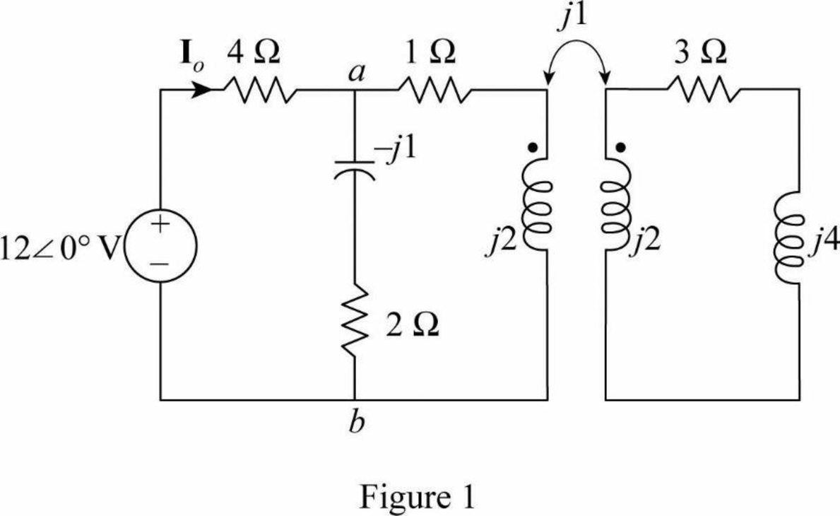
Modify the Figure 13.94 by transforming the time-domain circuit with coupled-coils to frequency domain of the circuit with coupled-coil. The frequency domain equivalent circuit is shown in Figure 1.
Write the expression for the impedance
Consider the expression for the reflected impedance
Substitute 2 for
Substitute
Simplify the Equation as follows.
Write the expression for the current
Substitute
The value of current
Convert the current from polar form to time domain form.
MATLAB code:
The MATLAB code using equations (3), (4) and (5) is,
M=0.5;
R2=3;
w=2;
L2=1;
ZL=4*j;
ZR=(w^2 * M^2)/(R2 + j*w*L2 + ZL);
Zab= (2-1*j)*(1+2*j+ZR)/(2-j+1+2*j+ZR)
Io=12/(Zab+4)
Then the MATLAB output is,
Zab = 1.4354 + 0.4639i
Io = 2.1918 - 0.1871i
Form the MATLAB output, impedance
Form the MATLAB output, current
The output is satisfied with analytical solution.
Conclusion:
Thus, the impedance
Want to see more full solutions like this?
Chapter 13 Solutions
Fundamentals of Electric Circuits


- The input impedance of an ac network can be measured with an ohmmeter. a.False b.True c.True if the ohmmeter is digital d.Sometimesarrow_forwardThe relationship between voltage and current is the same for two opposite directions of current in case ofchoose below bilateral network active network unilateral network passive networkarrow_forwardAnalyze the following AC networks, define and calculate all voltages, resistances (if necessary) and ampers! 120 j6 2 50/0arrow_forward
- Electric Circuit Analysis 2020/2021 Doaa Hakim H.W. Find the current I in the following network: v = 10/20° V ZR = 20 Z = j2N Z = 40arrow_forwardWhat values of Lz, Ly, and L3 are required if the two networks in Fig. 13.66 are to be equivalent?arrow_forwardFind the Thevenin equivalent for the circuit in Fig. 13.84 at terminals a-b.arrow_forward
- 13. Applying Thevenin’s theorem, calculate the current (showing its direction) in the 13 ohms resistor of circuit given in Figure 13. [Ans: 168.7 V; and 8.31A]arrow_forwardCalculate L for the coil if the induced emf is measured to be 2 V for a coil with bod tune when the current change within 0.1s from zero to 5 A. a. 400 Ⓒb. 200 H 02x10-H d4x10²4 thenarrow_forward11. Two coupled coils have self-inductances L1 = 2 H and L2 = 0.5 H, and a coefficient of coupling K = 0.9. Determine the turns ratio N1/N2 of the two coils.arrow_forward
 Introductory Circuit Analysis (13th Edition)Electrical EngineeringISBN:9780133923605Author:Robert L. BoylestadPublisher:PEARSON
 Delmar's Standard Textbook Of ElectricityElectrical EngineeringISBN:9781337900348Author:Stephen L. HermanPublisher:Cengage Learning
 Programmable Logic ControllersElectrical EngineeringISBN:9780073373843Author:Frank D. PetruzellaPublisher:McGraw-Hill Education
 Fundamentals of Electric CircuitsElectrical EngineeringISBN:9780078028229Author:Charles K Alexander, Matthew SadikuPublisher:McGraw-Hill Education
 Electric Circuits. (11th Edition)Electrical EngineeringISBN:9780134746968Author:James W. Nilsson, Susan RiedelPublisher:PEARSON
 Engineering ElectromagneticsElectrical EngineeringISBN:9780078028151Author:Hayt, William H. (william Hart), Jr, BUCK, John A.Publisher:Mcgraw-hill Education,