Videos
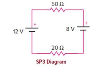
In the circuit shown, the 8-V battery is opposing the 12-V battery as they are positioned. The total voltage of the two batteries will be found by subtracting.
a. What is the current flowing around the circuit?
b. What is the voltage difference across the 20 Ω resistor?
c. What is the power delivered by the 12-V battery?
d. Is the 12-V battery discharging or charging in this arrangement?
(a)
The current flowing in the circuit.
Answer to Problem 3SP
The current through the circuit is
Explanation of Solution
Given info: The given circuit is shown below.
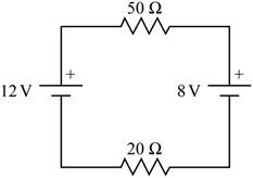
The two batteries in the given circuit have opposite polarity in the circuit. So the net potential difference of the circuit will be the difference of the two potential of the two batteries.
Write the formula for the net potential difference of the circuit.
Here,
The two resistance in the circuit are in series.
Write the formula for the equivalent resistance of the two resistances.
Here,
Write the formula for current.
Here,
Substitute the expression for
Substitute
Conclusion:
The current through the circuit is
(b)
The voltage difference across the
Answer to Problem 3SP
The voltage difference across the
Explanation of Solution
Given info: The given circuit is shown below.

The two batteries in the given circuit have opposite polarity in the circuit. So the net potential difference of the circuit will be the difference of the two potential of the two batteries.
Write the formula for the voltage difference across a resistor when two resistors are in series.
Here,
Substitute
Conclusion:
The voltage difference across the
(c)
The power delivered by the battery with voltage
Answer to Problem 3SP
The power delivered by the battery with voltage
Explanation of Solution
Given info: The given circuit is shown below.
Write the formula for the power delivered.
Here,
From section (a) the current in the circuit is
Substitute
Conclusion:
The power delivered by the battery with voltage
(d)
Whether the battery with voltage
Answer to Problem 3SP
The battery with voltage
Explanation of Solution
Given info: The given circuit is shown below.
The overall voltage of the circuit is
Thus the battery with voltage
Conclusion:
The battery with voltage
Want to see more full solutions like this?
Chapter 13 Solutions
Physics of Everyday Phenomena


- A 1,00-?O voltmeter is placed in parallel with a 75.0kresistor in a circuit, (a) Draw a circuit diagram of the connection, (b) What is the resistance of the combination? If the voltage across the combination is kept the same as it was across the 75.0-kresistor alone, what is the percent increase in current? (d) If the current through the combination is kept the same as it was through the 75.0-kresistor alone, what is the percentage decrease in voltage? (e) Are the changes found in parts (c) and (d) significant? Discuss.arrow_forwardConsider the circuit below. The capacitor has a capacitance of 10 mF. The switch is closed and after a long time the capacitor is fully charged, (a) What is the current through each resistor a long time after the switch is closed? (b) What is the voltage across each resistor a long rime after the switch is closed? (c) What is the voltage across the capacitor a long time after the switch is closed? (d) What is the charge on the capacitor a long time after the switch is closed? (e) The switch is then opened. The capacitor discharges through the resistors. How long from the time before the current drops to one fifth of the initial value?arrow_forward(a) A defibrillator sends a 6.00-A current through the chest of a patient by applying a 10,000-V potential as in the figure below. What is the resistance of the path? (b) The defibrillator paddles make contact with the patient through a conducting gel that greatly reduces the path resistance. Discuss the difficulties that would ensue if a larger voltage were used to produce the same current through the patient, but with the path having perhaps 50 times the resistance. (Hint: The current must be about the same, so a higher voltage would imply greater power. Use this equation for power: P=I2 RP = .)arrow_forward
- The circuit in Figure P27.34a consists of three resistors and one battery with no internal resistance. (a) Find the current in the 5.00- resistor. (b) Find the power delivered to the 5.00- resistor. (c) In each of the circuits in Figures P27.34b, P27.34c, and P27.34d, an additional 15.0-V battery has been inserted into the circuit. Which diagram or diagrams represent a circuit that requires the use of Kirchhoffs rules to find the currents? Explain why. (d) In which of these three new circuits is the smallest amount of power delivered to the 10.0- resistor? (You need not calculate the power in each circuit if you explain your answer.) Figure P27.34arrow_forwardThe- pair of capacitors in Figure P28.63 are fully charged by a 12.0-V battery. The battery is disconnected, and the switch is then closed. Alter 1.00 ms has elapsed, (a) how much charge remains 011 the 3.00-F capacitor? (b) How much charge remains on the 2.00-F capacitor? (c) What is the current in the resistor at this time?arrow_forwardA clock battery wears out after moving 10,000 C of charge through the clock at a rate of 0.500 mA. (a) How long did the clock run? (b) How many electrons per second flowed?arrow_forward
- The circuit in Figure P27.35 has been connected for several seconds. Find the current (a) in the 4.00-V battery, (b) in the 3.00- resistor, (c) in the 8.00-V battery, and (d) in the 3.00-V battery. (e) Find the charge on the capacitor. Figure P27.35arrow_forwardA 12-V car battery is used to power a 20.00-W, 12.00-V lamp during the physics club camping trip/star party. The cable to the lamp is 2.00 meters long, 14-gauge copper wire with a charge density of n=9.501028m3 . (a) What is the current draw by the lamp? (b) How long would it take an electron to get from the battery to the lamp?arrow_forwardA homemade capacitor is constructed of 2 sheets of aluminum foil with an area of 2.00 square meters, separated by paper, 0.05 mm thick, of the same area and a dielectric constant of 3.7. The homemade capacitor is connected in series with a 100,00- resistor, a switch, and a 6.00-V voltage source, (a) What is the RC time constant of the circuit? (b) What is the initial current through the circuit, when the switch is closed? (c) How long does it take the current to reach one third of its initial value?arrow_forward
- The rather simple circuit shown below is known as a voltage divider. The symbol consisting of three horizontal lines is represents “ground” and can be defined as the point where the potential is zero. The voltage divider is widely used in circuits and a single voltage source can be used to provide reduced voltage to a load resistor as shown in the second part of the figure, (a) What is the output voltage Vout of circuit (a) in terms of R1,R2,andVin (b) What is the output voltage Vout of circuit (b) in terms of R1,R2,RLandVinarrow_forwardFor the circuit shown in Figure P28.24, calculate (a) the current in the 2.00-11 resistor and (b) the potential difference between points a and b.arrow_forwardThree identical 60.0-W, 120-V lightbulbs are connected across a 120-V power source as shown in Figure P28.72. Assuming the resistance of each lightbulb is constant (even though in reality the resistance might increase markedly with current), find (a) the total power supplied by the power source and (b) the potential difference across each lightbulb.arrow_forward
 Physics for Scientists and Engineers with Modern ...PhysicsISBN:9781337553292Author:Raymond A. Serway, John W. JewettPublisher:Cengage Learning
 College PhysicsPhysicsISBN:9781305952300Author:Raymond A. Serway, Chris VuillePublisher:Cengage Learning
 Physics for Scientists and EngineersPhysicsISBN:9781337553278Author:Raymond A. Serway, John W. JewettPublisher:Cengage Learning
 Principles of Physics: A Calculus-Based TextPhysicsISBN:9781133104261Author:Raymond A. Serway, John W. JewettPublisher:Cengage Learning
 Glencoe Physics: Principles and Problems, Student...PhysicsISBN:9780078807213Author:Paul W. ZitzewitzPublisher:Glencoe/McGraw-Hill