Videos
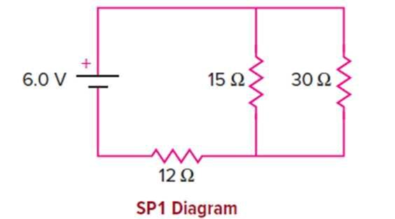
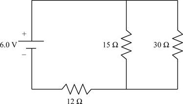
In the circuit shown, the internal resistance of the battery can be considered negligible.
a. What is the equivalent resistance of the two-resistor parallel combination?
b. What is the total current flowing through the battery?
c. What is the voltage drop across the 12-ohm resistor?
d. What is the voltage drop across the 15-ohm resistor?
e. What is the current flowing through the 15 Ω resistor?
f. What is the power dissipated in the 12 Ω resistor?
g. Is the current flowing through the 12 Ω resistor greater or less than that flowing through the 15 Ω resistor? Explain.
(a)
The equivalent resistance of the two parallel resistors.
Answer to Problem 1SP
The equivalent resistance of the two parallel resistors is
Explanation of Solution
Given info: The given circuit is shown below.

In the given circuit the resistances
Write the formula for the equivalent resistance of two resistances connected in parallel.
Here,
Substitute
Conclusion:
The equivalent resistance of the two parallel resistors is
(b)
The total current flowing in the circuit.
Answer to Problem 1SP
The total current through the circuit is
Explanation of Solution
Given info: The given circuit is shown below.
In the given circuit the resistances
Write the formula for the total resistance of the circuit.
Here,
Write the formula for the total current in the circuit.
Here,
Substitute the expression of
From section (a) the equivalent resistance of the two parallel resistances is
Substitute
Conclusion:
The total current through the circuit is
(c)
The voltage drop across
Answer to Problem 1SP
The voltage drop across
Explanation of Solution
Given info: The given circuit is shown below.

In the given circuit the resistances
The voltage of the battery will get distributed among the
Write the formula for the voltage across the
Here,
From section (a) the equivalent resistance of the parallel connection is
Substitute
Conclusion:
The voltage drop across
(d)
The voltage drop across
Answer to Problem 1SP
The voltage drop across
Explanation of Solution
Given info: The given circuit is shown below.
In the given circuit the resistances
The voltage of the battery will get distributed among the
The voltage drop across
Write the formula for the voltage across the parallel connection of
Here,
From section (c) the voltage across the series resistor is
Substitute
Conclusion:
The voltage drop across
(e)
The current flowing through
Answer to Problem 1SP
The current flowing through
Explanation of Solution
Given info: The given circuit is shown below.

In the given circuit the resistances
Write the formula for current.
Here,
The voltage drop across
Substitute
Conclusion:
The current flowing through
(f)
The power dissipated in
Answer to Problem 1SP
The power dissipated in
Explanation of Solution
Given info: The given circuit is shown below.
In the given circuit the resistances
Write the formula for power.
Here,
From section (c) the voltage drop across
Substitute
Conclusion:
The power dissipated in
(g)
Whether the current through
Answer to Problem 1SP
The current through
Explanation of Solution
Given info: The given circuit is shown below.
In the given circuit the resistances
Since the current is a conserved quantity, in the given circuit, the current through
Conclusion:
The current through
Want to see more full solutions like this?
Chapter 13 Solutions
Physics of Everyday Phenomena


- For the purpose of measuring the electric resistance of shoes through the body of the wearer standing on a metal ground plate, the American National Standards Institute (ANSI) specifies the circuit shown in Figure P27.14. The potential difference V across the 1.00-M resistor is measured with an ideal voltmeter. (a) Show that the resistance of the footwear is Rshoes=50.0VVV (b) In a medical test, a current through the human body should not exceed 150 A. Can the current delivered by the ANSI-specified circuit exceed 150 A? To decide, consider a person standing barefoot on the ground plate. Figure P27.14arrow_forwardConsider the circuit shown in Figure P28.21 on page 860. (a) Find the voltage across the 3.00-0 resistor, (b) Find the current in the 3.00-12 resistor.arrow_forwardA homemade capacitor is constructed of 2 sheets of aluminum foil with an area of 2.00 square meters, separated by paper, 0.05 mm thick, of the same area and a dielectric constant of 3.7. The homemade capacitor is connected in series with a 100,00- resistor, a switch, and a 6.00-V voltage source, (a) What is the RC time constant of the circuit? (b) What is the initial current through the circuit, when the switch is closed? (c) How long does it take the current to reach one third of its initial value?arrow_forward
- Why is the following situation impossible? A technician is testing a circuit that contains a resistance R. He realizes that a better design for the circuit would include a resistance 73R rather than R. He has three additional resistors, each with resistance R. By combining these additional resistors in a certain combination that is then placed in series with the original resistor, he achieves the desired resistance.arrow_forward(a) A defibrillator sends a 6.00-A current through the chest of a patient by applying a 10,000-V potential as in the figure below. What is the resistance of the path? (b) The defibrillator paddles make contact with the patient through a conducting gel that greatly reduces the path resistance. Discuss the difficulties that would ensue if a larger voltage were used to produce the same current through the patient, but with the path having perhaps 50 times the resistance. (Hint: The current must be about the same, so a higher voltage would imply greater power. Use this equation for power: P=I2 RP = .)arrow_forwardThree 100- resistors are connected as shown in Figure P21.41 The maximum power that can safely be delivered to any one resistor is 25.0 W. (a) What is the maximum potential difference that can be applied to the terminals a and b? (b) For the voltage determined in part (a), what is the power delivered to each resistor? (c) What is the total power delivered to the combination of resistors?arrow_forward
- A resistor of an unknown resistance is placed in an insulated container filled with 0.75 kg of water. A voltage source is connected in series with the resistor and a current of 1.2 amps flows through the resistor for 10 minutes. During this time, the temperature of the water is measured and the temperature change during this time is T10.00C . (a) What is the resistance of the resistor? (b) What is the voltage supplied by the power supply?arrow_forwardA battery with an internal resistance of 10.0 produces an open circuit voltage of 12.0 V. A variable load resistance with a range from 0 to 30.0 is connected across the battery. (Note: A battery has a resistance that depends on the condition of its chemicals and that increases as the battery ages. This internal resistance can be represented in a simple circuit diagram as a resistor in series with the battery.) (a) Graph the power dissipated in the load resistor as a function of the load resistance. (b) With your graph, demonstrate the following important theorem: The power delivered to a load is a maximum if the load resistance equals the internal resistance of the source.arrow_forwardThe circuit in Figure P27.34a consists of three resistors and one battery with no internal resistance. (a) Find the current in the 5.00- resistor. (b) Find the power delivered to the 5.00- resistor. (c) In each of the circuits in Figures P27.34b, P27.34c, and P27.34d, an additional 15.0-V battery has been inserted into the circuit. Which diagram or diagrams represent a circuit that requires the use of Kirchhoffs rules to find the currents? Explain why. (d) In which of these three new circuits is the smallest amount of power delivered to the 10.0- resistor? (You need not calculate the power in each circuit if you explain your answer.) Figure P27.34arrow_forward
- A circuit contains a D-cell battery, a switch, a 20- resistor, and three 20-mF capacitors. The capacitors are connected in parallel, and the parallel connection of capacitors are connected in series with the switch, the resistor and the battery, (a) What is die equivalent capacitance of the circuit? (b) What is the KC time constant? (c) How long before the current decreases to 50% of the initial value once the switch is closed?arrow_forwardConsider the circuit below. The capacitor has a capacitance of 10 mF. The switch is closed and after a long time the capacitor is fully charged, (a) What is the current through each resistor a long time after the switch is closed? (b) What is the voltage across each resistor a long rime after the switch is closed? (c) What is the voltage across the capacitor a long time after the switch is closed? (d) What is the charge on the capacitor a long time after the switch is closed? (e) The switch is then opened. The capacitor discharges through the resistors. How long from the time before the current drops to one fifth of the initial value?arrow_forwardConsider the circuits shown below, (a) What is the current through each resistor in part (a)? (b) What is the current through each resistor in part (b)? (c) What is the power dissipated or consumed by each circuit? (d) What is the power supplied to each circuit?arrow_forward

 College PhysicsPhysicsISBN:9781285737027Author:Raymond A. Serway, Chris VuillePublisher:Cengage Learning
 College PhysicsPhysicsISBN:9781305952300Author:Raymond A. Serway, Chris VuillePublisher:Cengage Learning
 Principles of Physics: A Calculus-Based TextPhysicsISBN:9781133104261Author:Raymond A. Serway, John W. JewettPublisher:Cengage Learning
 Physics for Scientists and EngineersPhysicsISBN:9781337553278Author:Raymond A. Serway, John W. JewettPublisher:Cengage Learning
 Physics for Scientists and Engineers with Modern ...PhysicsISBN:9781337553292Author:Raymond A. Serway, John W. JewettPublisher:Cengage Learning