
Loose Leaf for Engineering Circuit Analysis Format: Loose-leaf
9th Edition
ISBN: 9781259989452
Author: Hayt
Publisher: Mcgraw Hill Publishers
expand_more
expand_more
format_list_bulleted
Videos
Textbook Question
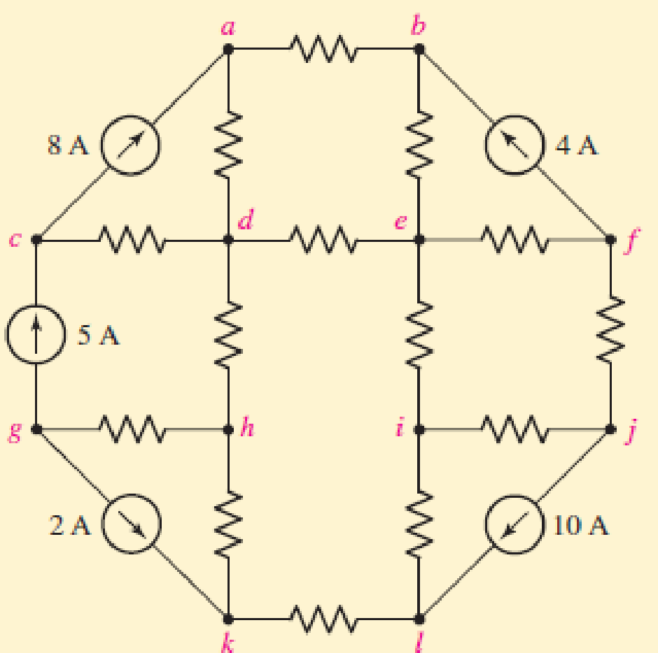
Chapter 12.1, Problem 1P
Let 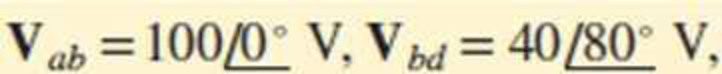 and
and 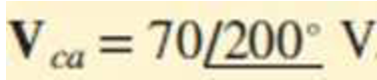 . Find (a) Vad; (b) Vbc; (c) Vcd.
Expert Solution & Answer
Want to see the full answer?
Check out a sample textbook solution
Students have asked these similar questions
! An enhancement-type NMOS transistor with
Vr = 2.5 V has its source grounded and a 4-V DC
source connected to the gate. Find the operating region
of the device if
a. vp = 0.5 V
b. vp = 1.5 V
Two 10-bit ADCs, one of successive approximation type and other of single
slope integrating type, take Ta and Tb time respectively to convert 3V analog
input signal to digital output. If the input analog signal is increased to 6V, the
approximate time taken by the two ADCs will respectively be
(a) What is the largest value of analog output
voltage in an 8 bit weighted DAC that produces 1v
for a digital input of 10111010?
(b)Draw the circuit diagram and waveforms of
NAND gate Monostable multivibrator whose time
period of 30Omsec. Calculate the value of
resistance and if the value of capacitance used is
900μF
Chapter 12 Solutions
Loose Leaf for Engineering Circuit Analysis Format: Loose-leaf
Ch. 12.1 - Let and . Find (a) Vad; (b) Vbc; (c) Vcd.Ch. 12.2 - Prob. 2PCh. 12.2 - Modify Fig. 12.9 by adding a 1.5 resistance to...Ch. 12.3 - A balanced three-phase three-wire system has a...Ch. 12.3 - A balanced three-phase three-wire system has a...Ch. 12.3 - Three balanced Y-connected loads are installed on...Ch. 12.4 - Each phase of a balanced three-phase -connected...Ch. 12.4 - Prob. 8PCh. 12.5 - Determine the wattmeter reading in Fig. 12.24,...Ch. 12.5 - Prob. 10P
Ch. 12 - Prob. 1ECh. 12 - Prob. 2ECh. 12 - Prob. 3ECh. 12 - Describe what is meant by a polyphase source,...Ch. 12 - Prob. 5ECh. 12 - Prob. 6ECh. 12 - Prob. 7ECh. 12 - Prob. 8ECh. 12 - Prob. 9ECh. 12 - Prob. 10ECh. 12 - The single-phase three-wire system of Fig. 12.31...Ch. 12 - Prob. 12ECh. 12 - Referring to the balanced load represented in Fig....Ch. 12 - Prob. 14ECh. 12 - Prob. 15ECh. 12 - Consider a simple positive phase sequence,...Ch. 12 - Assume the system shown in Fig. 12.34 is balanced,...Ch. 12 - Repeat Exercise 17 with Rw = 10 , and verify your...Ch. 12 - Prob. 19ECh. 12 - Prob. 20ECh. 12 - Prob. 21ECh. 12 - Prob. 22ECh. 12 - A three-phase system is constructed from a...Ch. 12 - Prob. 24ECh. 12 - Each load in the circuit of Fig. 12.34 is composed...Ch. 12 - Prob. 26ECh. 12 - Prob. 27ECh. 12 - A three-phase load is to be powered by a...Ch. 12 - For the two situations described in Exercise 28,...Ch. 12 - Prob. 30ECh. 12 - Prob. 31ECh. 12 - Prob. 32ECh. 12 - Repeat Exercise 32 if Rw = 1 . Verify your...Ch. 12 - Prob. 34ECh. 12 - Prob. 35ECh. 12 - Prob. 36ECh. 12 - A wattmeter is connected into the circuit of Fig....Ch. 12 - Find the reading of the wattmeter connected in the...Ch. 12 - (a) Find both wattmeter readings in Fig. 12.39 if...Ch. 12 - Circuit values for Fig. 12.40 are , , , , . Find...Ch. 12 - Prob. 41ECh. 12 - Prob. 42ECh. 12 - (a) Is the load represented in Fig. 12.41...Ch. 12 - Prob. 44E
Knowledge Booster


Learn more about
Need a deep-dive on the concept behind this application? Look no further. Learn more about this topic, electrical-engineering and related others by exploring similar questions and additional content below.Similar questions
- Derive the equation, where, given the circuit VCoswt -VCoswt VoC Carrow_forwardHow can you measure the value of Vp or VGSoff and IDSS experimentally?arrow_forwarddiode-connected NMOS device as shown below with VDD = 3.6 V and RL following parameters: VTH Given the NMOS common source amplifier degenerated by a 8.5 kn, please answer the following questions. Note that M₁ and M₂ have the 0.5V, k = 5004, and A = 0.001V-1. Also note that the DC input voltage is set such that the gate-to-source voltage of M2 is at VDD. Express all your answers up to THREE decimal places. Vdd T RL (0.5 pt) ID1,Q (0.5 pt) VDS1,Q (0.2 pt) VGS1,Q M1 (0.2 pt) gm1 (0.2 pt) rol (0.2 pt) 9m2 M2 = 1. Determine the DC operating point of M₁. μA V O VO 2. (0.2 pt) What is the DC input voltage, VIN? 3. What are the small signal parameters of M₁? mS ΜΩ mS V 4. Derive the two-port parameters of the given source-degenerated CS amplifier. You may assume that rol » 1. (0.8 pt) Gm (0.8 pt) Ro (0.4 pt) Av ms ΚΩarrow_forward
- Can you draw its equivalent circuit for furtger understanding and easy analysis. Also can you determine if Vcb and Vce is forward or reverse?arrow_forwardGiven the NMOS common source amplifier degenerated by a diode-connected NMOS device as shown below with VDD = 3.6 V and R₁ = 8.5 kn, please answer the following questions. Note that M₁ and M₂ have the following parameters: VTH = 0.5V, k = 50044, and X = 0.001V-¹. Also note that the DC input voltage is set such that the gate-to-source voltage of M2 is at VDD. Express all your answers up to THREE decimal places. Vdd VIO RL M1 9m1 Tol 9m2 M2 -o vo What is the DC input voltage, VIN? What are the small signal parameters of M₁? ms | ΜΩ mSarrow_forwardthe circuit described in the SOP terms using 2-input NAND functions only. F(A, B, C, D) = Em(2,3,4,5,6, 9, 12, 13)arrow_forward
- can u help me with this problem, i need to find Vce and Vbc. The transistor model is 2n2218. TYIAarrow_forwardThe following are the required circuit parameters for the T1 transistor in the following circuit. VBE=0.7 V, β=120, Cbc=Cμ=100pF, Cπ=Cbe=220pF, VA=∞, VT=26mV, and ro negligence; a) Find IB, IC and IE currents. b) Find VB, VC, VE and VCE voltages. c) Find Ri input resistance. d) Find ro output resistance. e) Find the lower cut frequencies.f) Find the upper cutting frequencies R:409arrow_forwardintegrated circuit families (RTL, DTL, TTL, CMOS) 4. Let vx = vy = 0.1V (Logic 0), B = 25 Determine all the currents and voltages in the circuit below: 11, 12, IR, IRC, iB, v1 & vo. Vcc=5 V VX Vy O- Dx KH KH Dy R = 4 ΚΩ D₁ VI 12 VB www iRC. Rg= 10 ΚΩ ≤Rc= 4 ΚΩ -OVOarrow_forward
- Consider the circuit below: Solve for the Gate-to-Source Voltage (VGS) in V, considering the values are: VDD = 16.63V, VGS(off) = -4.55V, IDSS = 10.33mA, Vs = 4.55V, RD = 2.44 kOhms, RS = 28.00 kOhmsarrow_forwardQ2- Design a voltage regulator that will maintain an output voltage of 20V across a 1K0 load with an input that will vary between 30V and 50V. That is, determine the proper value of Rs and the maximum current /ZM.arrow_forwardA JFET produces gate current of 1.5nA when gate is reverse biased with 6V. Calculate the value of resistance between gate and source. a. 4.5 GQ b. 7.5 GQ C. 4 GQ d. 0.25 GQarrow_forward
arrow_back_ios
SEE MORE QUESTIONS
arrow_forward_ios
Recommended textbooks for you
 Introductory Circuit Analysis (13th Edition)Electrical EngineeringISBN:9780133923605Author:Robert L. BoylestadPublisher:PEARSON
 Delmar's Standard Textbook Of ElectricityElectrical EngineeringISBN:9781337900348Author:Stephen L. HermanPublisher:Cengage Learning
 Programmable Logic ControllersElectrical EngineeringISBN:9780073373843Author:Frank D. PetruzellaPublisher:McGraw-Hill Education
 Fundamentals of Electric CircuitsElectrical EngineeringISBN:9780078028229Author:Charles K Alexander, Matthew SadikuPublisher:McGraw-Hill Education
 Electric Circuits. (11th Edition)Electrical EngineeringISBN:9780134746968Author:James W. Nilsson, Susan RiedelPublisher:PEARSON
 Engineering ElectromagneticsElectrical EngineeringISBN:9780078028151Author:Hayt, William H. (william Hart), Jr, BUCK, John A.Publisher:Mcgraw-hill Education,
Introductory Circuit Analysis (13th Edition)
Electrical Engineering
ISBN:9780133923605
Author:Robert L. Boylestad
Publisher:PEARSON
Delmar's Standard Textbook Of Electricity
Electrical Engineering
ISBN:9781337900348
Author:Stephen L. Herman
Publisher:Cengage Learning
Programmable Logic Controllers
Electrical Engineering
ISBN:9780073373843
Author:Frank D. Petruzella
Publisher:McGraw-Hill Education
Fundamentals of Electric Circuits
Electrical Engineering
ISBN:9780078028229
Author:Charles K Alexander, Matthew Sadiku
Publisher:McGraw-Hill Education
Electric Circuits. (11th Edition)
Electrical Engineering
ISBN:9780134746968
Author:James W. Nilsson, Susan Riedel
Publisher:PEARSON
Engineering Electromagnetics
Electrical Engineering
ISBN:9780078028151
Author:Hayt, William H. (william Hart), Jr, BUCK, John A.
Publisher:Mcgraw-hill Education,
Introduction to Logic Gates; Author: Computer Science;https://www.youtube.com/watch?v=fw-N9P38mi4;License: Standard youtube license