
Concept explainers
Videos
(a) Find both wattmeter readings in Fig. 12.39 if VA = 100∠0 ° V rms, VB = 50∠90° V rms, ZA = 10 − j10 Ω, ZB = 8 + j6 Ω, and ZC = 30 + j10 Ω. (b) Is the sum of these readings equal to the total power taken by the three loads? Verify your answer with an appropriate simulation.
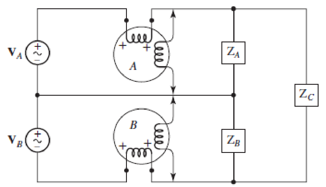
■ FIGURE 12.39
a.
Find the wattmeter readings in the circuit of Figure 12.39.
Answer to Problem 39E
The reading of wattmeter
Explanation of Solution
Given data:
The load impedance are
Calculation:
The given figure with mesh currents is shown in Figure 1.
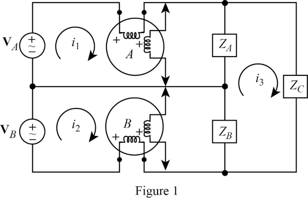
Apply Kirchhoff’s voltage law to the loop with current
Apply Kirchhoff’s voltage law to the loop with current
Apply Kirchhoff’s voltage law to the loop with current
Rearrange equation (1).
Substitute equation (4) in (3).
Simplify the equation as follows.
Substitute equation (5) in (4).
Substitute equation (6) in (2).
Simplify the equation as follows.
Substitute
Substitute
Calculate the power delivered by phase A as follows.
Calculate the power delivered by phase B as follows.
Conclusion:
Thus, the reading of wattmeter
b.
Verify that the sum of the wattmeter reading is equal to the total power taken by the three loads using LTspice.
Explanation of Solution
Formula used:
Write the expression for inductive reactance.
Here,
Write the expression for capacitive reactance.
Here,
Calculation:
Let us assume that the angular frequency
Substitute
Substitute
Substitute
LTspice Simulation:
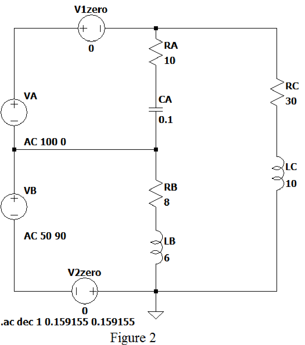
Draw the given figure in LTspice as shown in Figure 2. V1 zero and V2 zero connected in the circuit to find the current flows through it.
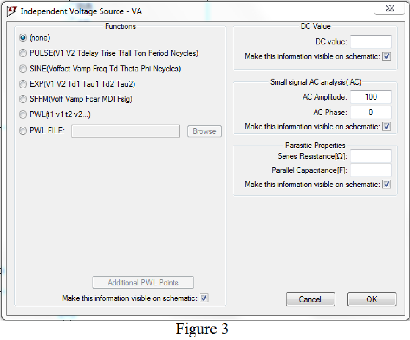
Set the values of voltages VA by right clicking on the voltage component, select none in “Functions” and enter the Small signal AC analysis parameters: AC amplitude as 100 for V1 as shown in Figure 3 for VA.
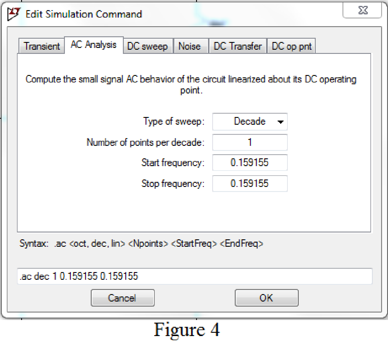
Now save the circuit, and open the “Edit Simulation command” choose AC analysis and select the sweep type as Decade, Number of points per decade 1, Start frequency and Stop frequency as 0.159155 Hz.
Now, run the simulation for the designed circuit. The output for the AC analysis will displays as shown in Figure 5.
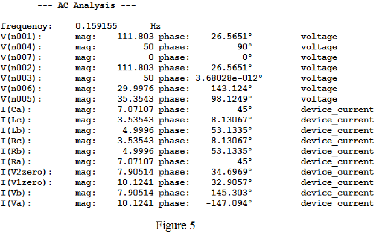
From above simulation results, the current flows through the load resistance are given below.
Calculate the power delivered to load
Calculate the power delivered to load
Calculate the power delivered to load
The total power delivered to the load is
The sum of the wattmeter reading is
Conclusion:
Thus, it is verified that sum of the wattmeter reading is equal to the total power taken by the three loads using LTspice.
Want to see more full solutions like this?
Chapter 12 Solutions
Loose Leaf for Engineering Circuit Analysis Format: Loose-leaf


- с Example: Delta-connected load consists of 10-Ohm resistance in series with 20-mH inductance. Source is Y-connected, abc sequence, 120-V rms, 60Hz. Determine laa, Ibb, Icc, lab, Ibc and ICA if: Van = 120/30°(V)rms Vcn a Van Vbn b IaA IbB I cc B IAB N IBC Z A ICA Carrow_forwardA generator is rated 100 MW, 13.8kV and 90% power factor. The effectiveresistance is 1.5 times the ohmic resistance. The ohmic resistance isobtained by connecting two terminals to a DC source. The current andvoltage are 87.6 A and 6 V respectively. What is the DC resistance perphase? What is the effective resistance per phase? Whole Solutionarrow_forwardProblem 2 For the system shown in Figure 12.5: a) Find Is. b) Find the average power delivered to each element. c) Find the reactive power associated with each element. d) Find PT, QT, and ST. e) Find the power factor seen by the source E. R₁ ww 392 + E = 50 V/60° R3 ww 492 R₂ 12 Ω Χ 16Ω Xc 802 Figure 12.5arrow_forward
- 2.1 Two power stations, A and B, are synchronized at 66 kV. They are inter-connected by a transmission line with an inductive reactance of 6.7-Ω and resistance of 3.5-Ω per phase. The voltage of power station A is advanced with an angle of 10.5 degrees with respect to the voltage of power station B. The loading of power station B has a real power of 200 MW. The respective loads of the two power stations are as follows: Power station A: 165 MVA at a power factor of 0.819 lagging. Power station B: The reactive power consumed by the load is 155 Mvar. *Round off to two decimal places in every question. Determine the following: 12.The interconnector current (kA)and it's angle 13.The reactive power received by power station A (MVar). 14.The active power received by power station B (MW).arrow_forward2.1 Two power stations, A and B, are synchronized at 66 kV. They are inter-connected by a transmission line with an inductive reactance of 6.7-Ω and resistance of 3.5-Ω per phase. The voltage of power station A is advanced with an angle of 10.5 degrees with respect to the voltage of power station B. The loading of power station B has a real power of 200 MW. The respective loads of the two power stations are as follows: Power station A: 165 MVA at a power factor of 0.819 lagging. Power station B: The reactive power consumed by the load is 155 Mvar. *Round off to two decimal places to every question 15.The active power loss within the interconnector (MW). 16.The reactive power loss within the interconnector (MVar). 17.The final loading of power station A (MVA) and it's anglearrow_forward2.1 Two power stations, A and B, are synchronized at 66 kV. They are inter-connected by a transmission line with an inductive reactance of 6.7-Ω and resistance of 3.5-Ω per phase. The voltage of power station A is advanced with an angle of 10.5 degrees with respect to the voltage of power station B. The loading of power station B has a real power of 200 MW. The respective loads of the two power stations are as follows:Power station A: 165 MVA at a power factor of 0.819 lagging.Power station B: The reactive power consumed by the load is 155 Mvar. *Round off to two decimal places to every question 18.The final loading of power station B (MVA) and it's angle 19.The reactive power received by power station A if the reactive power loading from power station A is to be reduced by 30% (MVar). 20.The required advancement angle at power station A to achieve the 30% reduction in reactive power loading of power station A (degrees).arrow_forward
- Choose the correct answer: Capacitors in AC circuits dissipate power in the form of heat Select one: O True O False Choose the correct answer: In a balanced three-phase system, phase shift between phase and line voltage is 30". Select one: O True O False What is the phase shift between a phase current and its voltage in a three-phase balanced system? O a. 90 O b. It can be anything, it depends on system parameters. O C. 120 Od 30°arrow_forwardFor single phase ac voltage controller, R=15ohm, f=50Hz and Vrms=230V and α=0,82 rad. Calculate the rms load voltage (V). In this question, take 2 digits after the comma and take pi = 3,14; enter your answer into the system in terms of the desired unit only as a number.solve the question by using the rules of power electronicsarrow_forward1. What is the main direct cause of reactive power in AC system? A. Resistance of transmission lines B. Inductance and capacitance in the loads C. Ideal transformer connected in the system D. Power produced by generator 2. "Reactive power in a system is dissipated generally as thermal energy?" A. TRUE B. FALSE 3. Which of the following statements are correct for three phase circuit: A. Sum of all the three phase currents is zero in unbalanced network B. Total power transfer to load is constant with time C. Neutral conductor is same size in terms of material used as in single phase conductors D. Net apparent power consumed is equal to real powerarrow_forward
- Homework problem: The per-phase equivalent circuit parameters of a 400 V, 33 kW, 60 Hz, star-connected, 4 pole, 1755 rpm 3-0 IM are: R1= 0.2 N, X1= j0.5 2, Xm= j20 2, R2 = 0.12, X2 = 0.2 N. If the mechanical losses (windage and friction) are 650 W and iron losses are 300 W, determine the following when the motor operates at full load at rated speed: (a) The synchronous speed. (b) The slip. (c) The input current and power factor. (d) The input power. (e) The useful mechanical power. (f) The output torque. (g) The motor efficiency. Use exact equivalent circuit and simplified equivalent circuit and give comments on the results obtained.arrow_forwardThe following information is given in connection with a load circuit consisting of two parallel branches: Z1 = 4.8/25° ohms, Z2 = 3.75/-72° ohms, l1 = 50 amperes, and l2 = 64 amperes. Calculate: a) the equivalent impedance; b) the total voltage; c) the currents 11 and 12 if the total voltage is used as reference; d) the total real, reactive, and apparent powers; e) the overall power factor. An impedance ZL = (11.5 + j10) ohms is connected in parallel with an impedance ZC = (8 – j20) ohms. Calculate: a) the conductance, susceptance, and admittance of each branch; b) the total conductance, susceptance, and admittance; c) the total current in polar form if the source voltage is used as the reference; d) the total real, reactive, and apparent powers; e) the overall power factor.arrow_forwardProblem 1 For the system shown in Figure 12.9: a) Find PT, QT, and ST. b) Draw the power triangle. c) Find the power factor seen by the source E. d) Find Is. + E 120 V/50° Load 1 1100 VAR (C) 750 W Load 2 950 VAR (L) 100 W Load 4 700 VAR (C) 200 W Load 3 Figure 12.9 1900 VAR (L) 500 Warrow_forward
 Introductory Circuit Analysis (13th Edition)Electrical EngineeringISBN:9780133923605Author:Robert L. BoylestadPublisher:PEARSON
 Delmar's Standard Textbook Of ElectricityElectrical EngineeringISBN:9781337900348Author:Stephen L. HermanPublisher:Cengage Learning
 Programmable Logic ControllersElectrical EngineeringISBN:9780073373843Author:Frank D. PetruzellaPublisher:McGraw-Hill Education
 Fundamentals of Electric CircuitsElectrical EngineeringISBN:9780078028229Author:Charles K Alexander, Matthew SadikuPublisher:McGraw-Hill Education
 Electric Circuits. (11th Edition)Electrical EngineeringISBN:9780134746968Author:James W. Nilsson, Susan RiedelPublisher:PEARSON
 Engineering ElectromagneticsElectrical EngineeringISBN:9780078028151Author:Hayt, William H. (william Hart), Jr, BUCK, John A.Publisher:Mcgraw-hill Education,