
Concept explainers
Videos
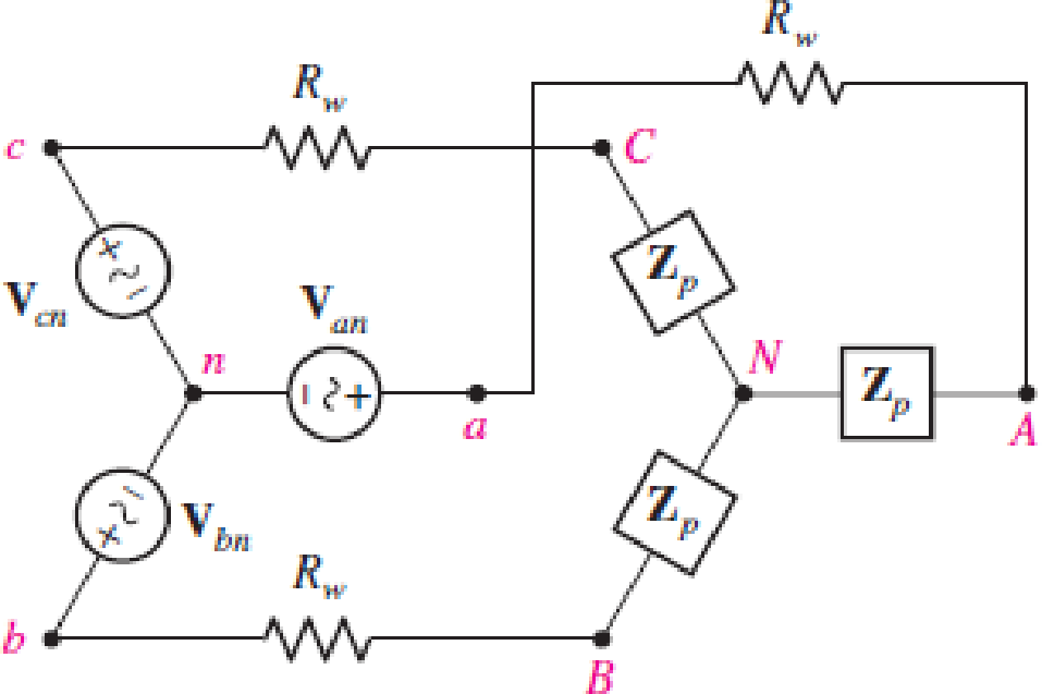
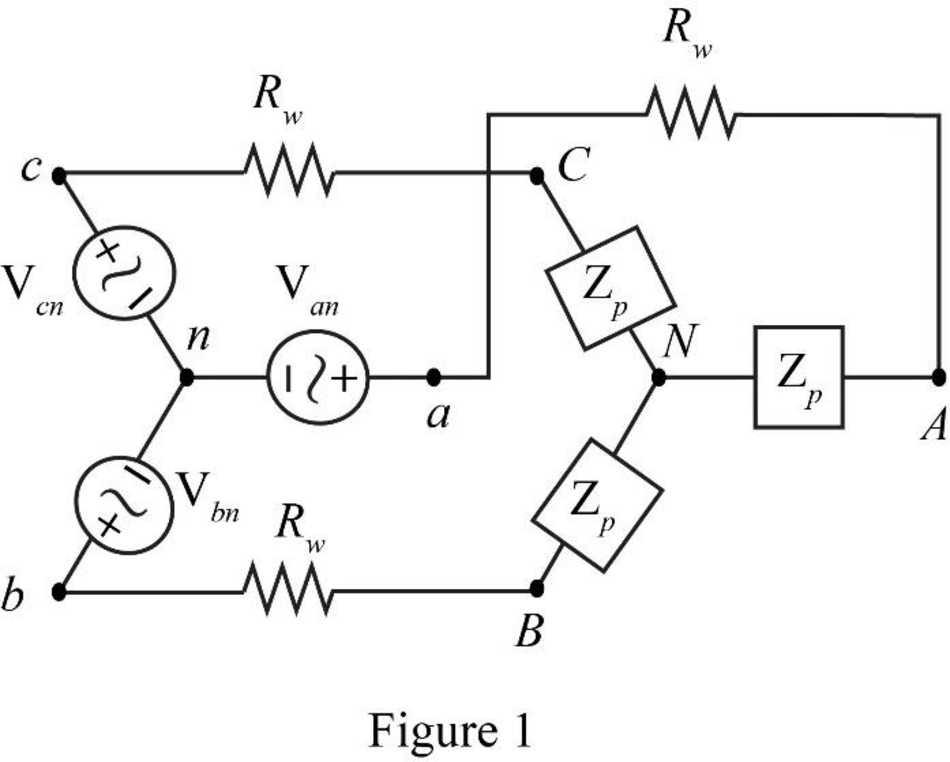
Assume the system shown in Fig. 12.34 is balanced, Rw = 0,  , and a positive phase sequence applies. Calculate all phase and line currents, and all phase and line voltages, if Zp is equal to (a) 1 kΩ; (b) 100 + j48 Ω; (c) 100 − j48 Ω.
(a)
All the line and phase currents and all the line and phase voltages for the given load impedance.
Answer to Problem 17E
The line and phase currents in sequence are
Explanation of Solution
Given data:
The resistance of the wire
The phase to neutral voltage
The load impedance
Calculation:
The system follows positive sequence hence the phase to neutral voltages will be,
For phase
For phase
The required diagram is shown in Figure 1.
The line voltage between phase
Substitute
The system follows positive sequence hence the line to line voltages will be,
All the phase and line voltages are independent of the impedance value and hence these values will remain same for all the values of load impedance
The conversion from
Hence, the load impedance
Since the given system is a star connected system, the phase currents will be equal to the line currents.
The phase
Here,
The phase
Substitute
The phase
Here,
The phase
Substitute
The phase
Here,
The phase
Substitute
Conclusion:
Therefore, the line and phase currents in sequence are
(b)
All the line and phase currents and all the line and phase voltages for the given load impedance.
Answer to Problem 17E
The line and phase currents in sequence are
Explanation of Solution
Given data:
The load impedance
Calculation:
All the phase and line voltages are independent of the impedance value and hence these values will remain same for all the values of load impedance
The phase
Here,
The phase
Substitute
The phase
Here,
The phase
Substitute
The phase
Here,
The phase
Substitute
Conclusion:
Therefore, the line and phase currents in sequence are
(c)
All the line and phase currents and all the line and phase voltages for the given load impedance.
Answer to Problem 17E
The line and phase currents in sequence are
Explanation of Solution
Given data:
The load impedance
Calculation:
All the phase and line voltages are independent of the impedance value and hence these values will remain same for all the values of load impedance
The phase
Here,
The phase
Substitute
The phase
Here,
The phase
Substitute
The phase
Here,
The phase
Substitute
Conclusion:
Therefore, the line and phase currents in sequence are
Want to see more full solutions like this?
Chapter 12 Solutions
Loose Leaf for Engineering Circuit Analysis Format: Loose-leaf


- Problem 2 For the system shown in Figure 12.5: a) Find Is. b) Find the average power delivered to each element. c) Find the reactive power associated with each element. d) Find PT, QT, and ST. e) Find the power factor seen by the source E. R₁ ww 392 + E = 50 V/60° R3 ww 492 R₂ 12 Ω Χ 16Ω Xc 802 Figure 12.5arrow_forwardThree Impedances each of (12 -j18)N are connected in mesh across a three-phase 420V ac supply. Determine the phase current, line current, active power, reactive power drawn from the supply. phase current (Ip) Line current real power reactive powerarrow_forwardThree Impedances each of (8 - j18) are connected in mesh across a three-phase 410V ac supply. Determine the phase current, line current, active power, reactive power drawn from supply. Also draw the Phasor diagram for the mesh connection and marks the Line current ,phase current line voltage and phase angle between phase current and pahse voltage. I phase current (Ip) Line current real power reactive powerarrow_forward
- Two loads are connected in parallel to a source of emf whose voltage is (110 + j63.5). if the branch currents are z1= (8 – j8) & ?2= (7.5 + j10). Calculate the following items below. a. Total current b. Equivalent impedance c. Total power d. Reactive powerarrow_forwardFind the line currents in the unbalanced three-phase circuit of Fig. 12.26 and the real power absorbed by the load. 220-120° rms V Figure 12.26 220/0° rms V 220/120⁰ rms V b -j5Q B A www j1092 1092 Carrow_forwardFor the following circuit, find (a) the load impedance required for maximum average power transfer and (b) the average power transferred to this load impedance. (a) - 2js 12V (b) Zjsr 24V 252 (+)arrow_forward
- Three Impedances each of (12-j16) Q are connected in mesh across a three-phase 435V ac supply. Determine the phase current, line current, active power, reactive power and apparent power drawn from supply. phase current (lp) Line current real power reactive power Apparent powerarrow_forward11.20 For the circuit shown in Fig. P11.20, find PSPICE a) the phase currents IAB, IBC, and ICA, MULTISIM b) the line currents IaA, IbB, and Icc when Z1 = 2.4 - j0.7 N, Z2 = 8 + j6 N, and Z3 = 20 + j0 N.arrow_forward20) Two AC generators A and B are in Parallel. Each generator has an emf of 1000V per phase and in phase, the phase impedance are ZA = 0.1+j2 ohms, ZB = 0.2+j3.2 ohms respectively. If the common load has an impedance of (2+j1) ohms per phase, solve the voltage per phase at the loadarrow_forward
- A balanced 3-phase Y-connected source 866V, 60Hz, feeds a A-connected loads (Zph=177- j2460) via a line. Each phase of the line is 1+j20. Phase-sequence is positive. Determine: 1) line and phase current; 2) power absorbed by the load; 3) power dissipated by the line. 192 C 5000 500/120 V 500-120° V Tab 1. 152 j20 voo -553.13" A j2 52 voo -52-66.87" A j20 000 -5.173.13: A B TAB 177 02 --j246 2 -j246 02 177 2 177 Ω -246 Q HE -ÏBC ICA VBC VCAarrow_forwardFor the circuit shown, find 1. a) the phase currents IAB, IBC, and ICA, 2. b) the line currents IaA, IbB, and IcC when Z1=2.4−j0.7 Ω, Z2=8+j6 Ω, and Z3=20+j0 Ω.arrow_forwardThree Impedances each of (14 – j18)N are connected in mesh across a three-phase 415V ac supply. Determine the phase current, line current, active power, reactive power drawn from supply. Also draw the Phasor diagram for the mesh connection and marks the Line current ,phase current line voltage and phase angle between phase current and pahse voltage. phase current (Ip) Line current real power reactive powerarrow_forward
 Introductory Circuit Analysis (13th Edition)Electrical EngineeringISBN:9780133923605Author:Robert L. BoylestadPublisher:PEARSON
 Delmar's Standard Textbook Of ElectricityElectrical EngineeringISBN:9781337900348Author:Stephen L. HermanPublisher:Cengage Learning
 Programmable Logic ControllersElectrical EngineeringISBN:9780073373843Author:Frank D. PetruzellaPublisher:McGraw-Hill Education
 Fundamentals of Electric CircuitsElectrical EngineeringISBN:9780078028229Author:Charles K Alexander, Matthew SadikuPublisher:McGraw-Hill Education
 Electric Circuits. (11th Edition)Electrical EngineeringISBN:9780134746968Author:James W. Nilsson, Susan RiedelPublisher:PEARSON
 Engineering ElectromagneticsElectrical EngineeringISBN:9780078028151Author:Hayt, William H. (william Hart), Jr, BUCK, John A.Publisher:Mcgraw-hill Education,