
Concept explainers
Videos
Use mesh analysis to find vo in the circuit of Fig. 10.78. Let vs1 = 120 cos (100t + 90°) V, vs2 = 80 cos 100/ V.
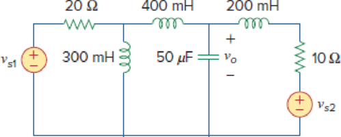
Figure 10.78
Find the voltage
Answer to Problem 30P
The value of voltage
Explanation of Solution
Given data:
Refer Figure 10.78 in the textbook for mesh analysis.
Formula used:
Write the expression to calculate impedance of the inductor.
Here,
Write the expression to calculate impedance of the capacitor.
Here,
Write the general representation of sinusoidal function.
Here,
Write the general expression to phasor transform of sinusoidal function from time domain to frequency domain.
Here,
Write the polar form representation of frequency domain.
Calculation:
Comparing given source voltage
Substitute
Comparing given source voltage
Substitute
Substitute
Substitute
Substitute
Substitute
The frequency domain representation of given figure with the representation of node voltage is shown in Figure 1.
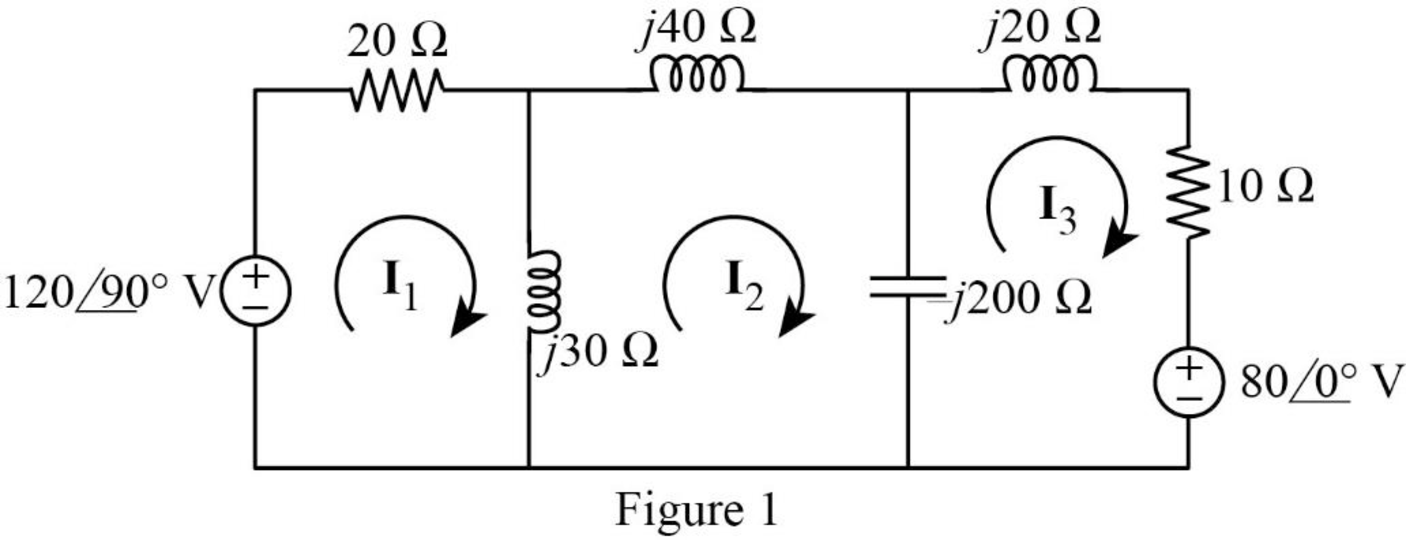
Apply Kirchhoff’s voltage law in the loop with current
Apply Kirchhoff’s voltage law in the loop with current
Apply Kirchhoff’s voltage law in the loop with current
MATLAB Code:
Solve the linear equations (5), (6) and (7) using MATLAB to find the mesh currents.
syms i1 i2 i3
eq1 = (2 + 3*1i)*i1 -3*1i*i2 +0*i3 == 12*1i;
eq2 = -3*i1 -13*i2 +20*i3 == 0;
eq3 = 0*i1 +20*1i*i2 +(1-18*1i)*i3 == -8;
sol = solve([eq1, eq2, eq3], [i1, i2, i3]);
val1 = sol.i1;
val2 = sol.i2;
val3 = sol.i3;
i1real=real(val1);
i1imag=imag(val1);
i2real=real(val2);
i2imag=imag(val2);
i3real=real(val3);
i3imag=imag(val3);
i1=sprintf('%.3f + %.3fi A', i1real, i1imag)
i2=sprintf('%.3f + %.3fi A', i2real, i2imag)
i3=sprintf('%.3f + %.3fi A', i3real, i3imag)
The command window output:
i1 = '2.0557 + 3.5651i A'
i2 = '0.4324 + 2.1946i A'
i3 = '0.5894 + 1.9612i A'
From Figure 1, write the expression for
Substitute
Represent the voltage in time domain.
Conclusion:
Therefore, the value of voltage
Want to see more full solutions like this?
Chapter 10 Solutions
Fundamentals of Electric Circuits


- g o HB Circuits the 10.64 For the circuit shown ir equivalent circuit at ti 3/60° A ) b b Figure 10,103 it in 10.65 C ompute i S c-d 0arrow_forwardQ10. If the impedance of a circuit = 20 – j10n, if a voltage source is connected across this impedance, which if the following statements is correct?arrow_forward10.4 Find the -1/4 system function for the following structure. + -5/2arrow_forward
- In the circuit of Fig. 10.77, (a) find values for I1, I2, and I3. (b) Show Vs, I1, I2, and I3 on a phasor diagram (scales of 50 V/in and 2 A/in work fine). (c) Find Is graphically and give its amplitude and phase angle.arrow_forwardProblem 10.025 - Mesh Analysis with voltage sources Determine the output current loin the circuit given below using mesh analysis, where Vs = 18 cos(2 t) V. Please report your answer so the magnitude is positive and all angles are in the range of negative 180 degrees to positive 180 degrees. 2 H Vs+ 492 www lo m : 0.25 F The output current lo= 6 sin 2t V cos(2t+ 9) A.arrow_forward10.23. Draw the block diagrams of both the direct forms I and II simulation diagrams for the systems with the following difference equations: (a) 2y[n]y[n 1] + 4y[n-2] = 5x[n] (b) 1 3]arrow_forward
- | Steady-State Analysis quivalent at terminals a-l 6Ω j2 Q ell e 10.24 ctice Prob. 10.8. +arrow_forward4. In a linear circuit, the voltage source is Vs = 12 sin(10°t + 24') V (a) What is the angular frequency of the voltage? (b) What is the frequency of the source? (c) Find the period of the voltage. (d) Find the Vrms value.arrow_forwardDetermine the Norton equivalent of the circuit in Fig. 10.30 as seen from terminals a-b. Use the equivalent to find Lo j2 52 10/0° V 892 www Figure 10.30 492 wwwww = 1Ω -j3Ω www 2/-90° A Answer: ZN I, 985.5/-2.101° mA. 10 Ω -j5 52 3.176 + j0.706 2. IN = 4.198/-32.68° A.arrow_forward
- 10.11 Consider the plots in Fig. 10.27. Identify if the gen set is being operated in a load-following or cycle-charging scheme. Explain your reasoning. gen set pmax gen load PV 4 12 16 20 con con 0:00 4:00 8:00 12:00 16:00 20:00 100 min 0:00 4:00 8:00 12:00 16:00 20:00 Time of Day (h) 47 Power (W) State-of-Charge (%) Converter Power (W)arrow_forwardObtain V, and I, in the circuit depicted in Fig. 10.40. 48/0°V :-j0.25 j22 V, j2 ae 12 ww ell 16/60°A :-j12 41,arrow_forwardProblem 10.049 - Source transformation in phasor circuits Using source transformation, find i in the circuit given in the figure. Take is 5Ω The value of i= 3Ω sin(200t+ 5 mH 1 mF 9) A. 8 sin (200t +30°) A.arrow_forward
 Introductory Circuit Analysis (13th Edition)Electrical EngineeringISBN:9780133923605Author:Robert L. BoylestadPublisher:PEARSON
 Delmar's Standard Textbook Of ElectricityElectrical EngineeringISBN:9781337900348Author:Stephen L. HermanPublisher:Cengage Learning
 Programmable Logic ControllersElectrical EngineeringISBN:9780073373843Author:Frank D. PetruzellaPublisher:McGraw-Hill Education
 Fundamentals of Electric CircuitsElectrical EngineeringISBN:9780078028229Author:Charles K Alexander, Matthew SadikuPublisher:McGraw-Hill Education
 Electric Circuits. (11th Edition)Electrical EngineeringISBN:9780134746968Author:James W. Nilsson, Susan RiedelPublisher:PEARSON
 Engineering ElectromagneticsElectrical EngineeringISBN:9780078028151Author:Hayt, William H. (william Hart), Jr, BUCK, John A.Publisher:Mcgraw-hill Education,