
Concept explainers
Videos
Using nodal analysis, find io(t) in the circuit in Fig. 10.60.
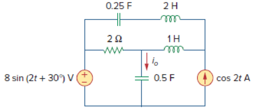
Figure 10.60
For Prob. 10.11.
Find the current
Answer to Problem 11P
The value of current
Explanation of Solution
Given data:
Refer Figure 10.60 in the textbook for nodal analysis.
Formula used:
Write the expression to calculate impedance of the inductor.
Here,
Write the expression to calculate impedance of the capacitor.
Here,
Write the general representation of sinusoidal function.
Here,
Write the general expression to phasor transform of sinusoidal function from time domain to frequency domain.
Here,
Write the polar form representation of frequency domain.
Calculation:
Comparing given source voltage
Substitute
Convert
Substitute
Substitute
Substitute
Substitute
The frequency domain representation of given figure with the representation of node voltage is shown in Figure 1.
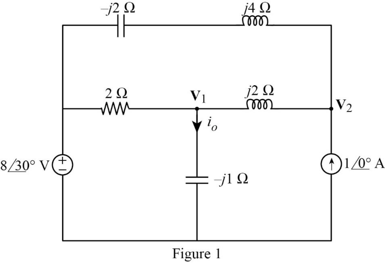
Apply Kirchhoff’s current law at node
Simplify the equation as follows.
Apply Kirchhoff’s current law at node
MATLAB Code:
Solve the two linear equations (5) and (6) using MATLAB to find the node voltages.
syms v1 v2
eq1 = (0.5 + 0.5*1i)*v1 +(0.5*1i)*v2 == 3.464 + 2*1i;
eq2 = (0.5*1i)*v1 +(-1*1i)*v2 == 3 + (-3.464*1i);
sol = solve([eq1, eq2], [v1, v2]);
val1 = sol.v1;
val2 = sol.v2;
v1real=real(val1);
v1imag=imag(val1);
v2real=real(val2);
v2imag=imag(val2);
v1=sprintf('%.3f + (%.3f)i V', v1real, v1imag)
v2=sprintf('%.3f + (%.3f)i V', v2real, v2imag)
The command window output:
v1 = '3.302 + (-4.417)i V'
From Figure 1, write the expression for
Substitute
Represent the current in time domain.
Conclusion:
Therefore, the value of current
Want to see more full solutions like this?
Chapter 10 Solutions
Fundamentals of Electric Circuits
Additional Engineering Textbook Solutions
Electric Circuits. (11th Edition)
Loose Leaf for Engineering Circuit Analysis Format: Loose-leaf
Principles and Applications of Electrical Engineering
Basic Engineering Circuit Analysis
Engineering Electromagnetics
Fundamentals of Applied Electromagnetics (7th Edition)


- Calculate current of inductor and voltage of capacitor in transient state after turning on the switch in the circuit of Fig. 10.25. Assume: R=5Ω, C=100μF, L=1H, e1(t)=10V, e2(t)=10V.arrow_forward0198% 10:15 Leila Hammadi B... 1 minute ago Given the following circuit with Is=40<30° mA Is 12:1 V 10002 Select one: O a. V, 120<60° V b. V,-480<30° V C. None of these d. V,-480<-30° V < O Oarrow_forwardDetermine the Norton equivalent of the circuit in Fig. 10.30 as seen from terminals a-b. Use the equivalent to find I ww IA -130 wwH ww 10A 10/0 V O 290 Aarrow_forward
- Determine the Norton equivalent of the circuit in Fig. 10.30 as seen from terminals a-b. Use the equivalent to find Io.arrow_forwardDetermine the Thevenin equivalent of the circuit in Fig. 10.27 as seen from the terminals a-b.arrow_forwardQ.4) For the power electronics circuit shown below, sketch the output voltage waveform (Vo) and hence find its average value. a = 80° R - 102 40V Vs = 200 sin cot Vo R = 102arrow_forward
- Determine the Norton equivalent of the circuit in Fig. 10.30 as seen from terminals a-b. Use the equivalent to find I ww ww wwHE 102 10/0 V 2-90° Aarrow_forward63. Use phasors and nodal analysis on the circuit of Fig. 10.65 to find V2. j3 0 5/90 A (* 30 O 10/0 Aarrow_forwardPRACTICE PROBLEM 10.7 Find I, in the circuit of Fig. 10.19 using the concept of source transfor- mation. 4/90° A 292 jlQ wwwm Answer: 3.288/99.46° A. 4Ω -j3 92 j5 92 Figure 10.19 For Practice Prob. 10.7. 192 -j2 92arrow_forward
- Im:_,m 10.70 For Prob. 1 g8Q Jj6Q 40 j5Q WWW—T WWA—T + + 4£45° A VIS 21Qe i 2V, ==-jlQ -2Q =V, Figure 10.67 For Prob. 10.18.arrow_forwardFind vo of the circuit of Fig. 10.13 using the superposition theorem. 2 H 1Ω 4Ω ww ll 2 sin 5t A 0.1 F 5 V 10 cos 2t Varrow_forward10.7 Use nodal analysis to find V in the circuit of Fig. 10.56. 120 -15° V 40 Ω j20 ≤2 V ww 6/30° A -j30 250 2arrow_forward
 Introductory Circuit Analysis (13th Edition)Electrical EngineeringISBN:9780133923605Author:Robert L. BoylestadPublisher:PEARSON
 Delmar's Standard Textbook Of ElectricityElectrical EngineeringISBN:9781337900348Author:Stephen L. HermanPublisher:Cengage Learning
 Programmable Logic ControllersElectrical EngineeringISBN:9780073373843Author:Frank D. PetruzellaPublisher:McGraw-Hill Education
 Fundamentals of Electric CircuitsElectrical EngineeringISBN:9780078028229Author:Charles K Alexander, Matthew SadikuPublisher:McGraw-Hill Education
 Electric Circuits. (11th Edition)Electrical EngineeringISBN:9780134746968Author:James W. Nilsson, Susan RiedelPublisher:PEARSON
 Engineering ElectromagneticsElectrical EngineeringISBN:9780078028151Author:Hayt, William H. (william Hart), Jr, BUCK, John A.Publisher:Mcgraw-hill Education,