(2) Calculate Zbus for the network shown at right, as follows. Show all steps of your calculations. j0.23 (a) Starting with an empty matrix, add bus 1 connected to ground through impedance j0.2 (1) (b) Add bus 2 connected to bus 1 through impedance j0.2 (c) Add bus 3 connected to ground through impedance j0.25 (d) Add impedance j0.4 between bus 2 and bus 3. (e) Add impedance j0.5 between bus 1 and bus 3.
(2) Calculate Zbus for the network shown at right, as follows. Show all steps of your calculations. j0.23 (a) Starting with an empty matrix, add bus 1 connected to ground through impedance j0.2 (1) (b) Add bus 2 connected to bus 1 through impedance j0.2 (c) Add bus 3 connected to ground through impedance j0.25 (d) Add impedance j0.4 between bus 2 and bus 3. (e) Add impedance j0.5 between bus 1 and bus 3.

Power System Analysis and Design (MindTap Course List)
6th Edition
ISBN:9781305632134
Author:J. Duncan Glover, Thomas Overbye, Mulukutla S. Sarma
Publisher:J. Duncan Glover, Thomas Overbye, Mulukutla S. Sarma
Chapter2: Fundamentals
Section: Chapter Questions
Problem 2.36P

Related questions
Question

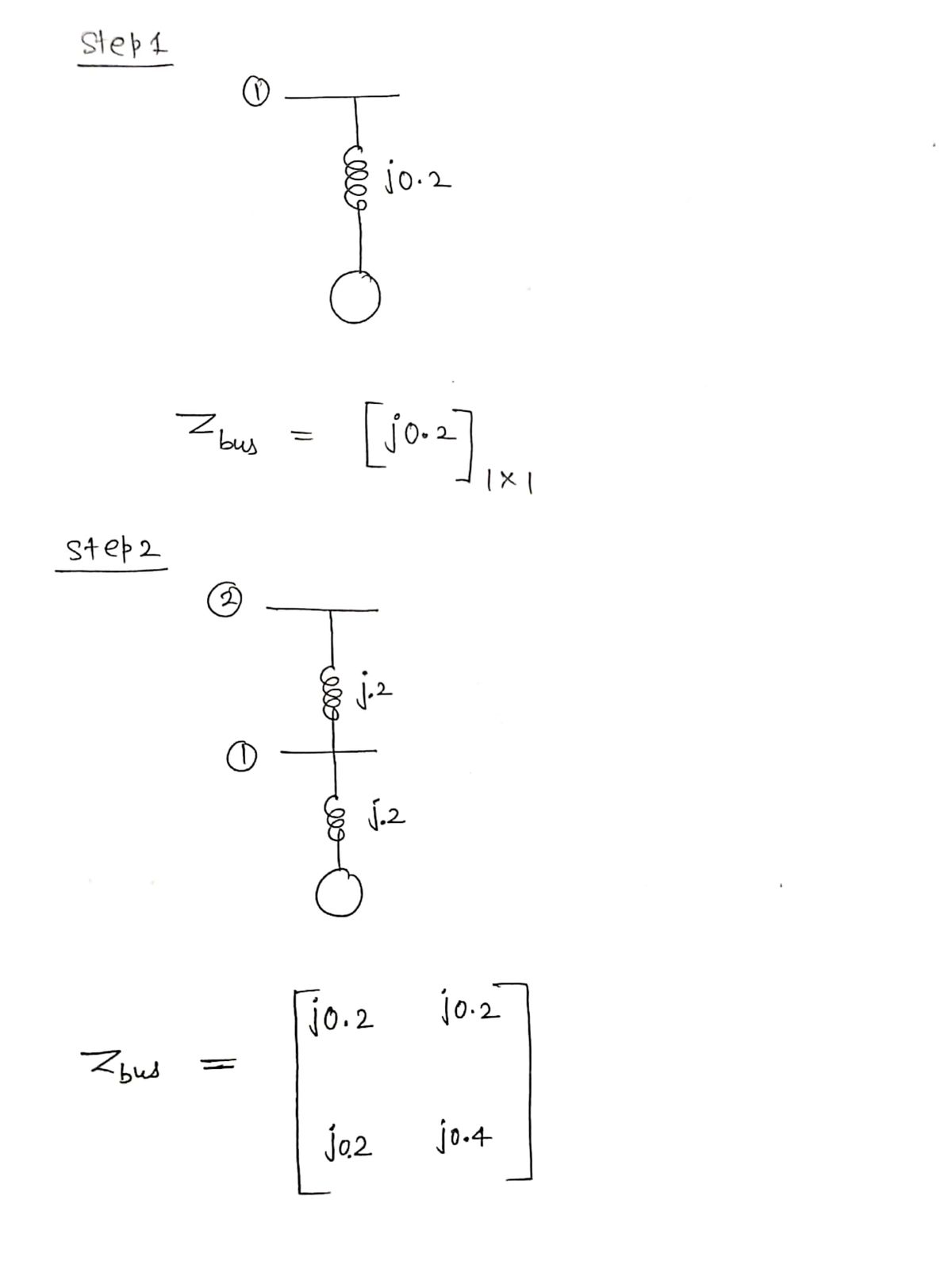
Transcribed Image Text:Calculate Zbus for the network shown at right, as follows.
Show all steps of your calculations.
j0.5
j0.23
3j0.4
(a) Starting with an empty matrix, add bus 1 connected to ground
through impedance j0.2
(1)
(3).
j0.2
j0.25
(b) Add bus 2 connected to bus 1 through impedance j0.2
(c) Add bus 3 connected to ground through impedance j0.25
(d) Add impedance j0.4 between bus 2 and bus 3.
(e) Add impedance j0.5 between bus 1 and bus 3.
(2)
Expert Solution
Step 1

Trending now
This is a popular solution!

Step by step
Solved in 5 steps with 5 images

Knowledge Booster


Learn more about
Need a deep-dive on the concept behind this application? Look no further. Learn more about this topic, electrical-engineering and related others by exploring similar questions and additional content below.Recommended textbooks for you
Power System Analysis and Design (MindTap Course …
Electrical Engineering
ISBN:
9781305632134
Author:
J. Duncan Glover, Thomas Overbye, Mulukutla S. Sarma
Publisher:
Cengage Learning
Power System Analysis and Design (MindTap Course …
Electrical Engineering
ISBN:
9781305632134
Author:
J. Duncan Glover, Thomas Overbye, Mulukutla S. Sarma
Publisher:
Cengage Learning