
Concept explainers
Videos
(a)
Calculate the energy stored in each energy storage element.
(a)
Answer to Problem 70E
The value of energy stored in the inductor
Explanation of Solution
Given data:
Refer to Figure 7.84 in the textbook.
Calculation:
The given circuit is redrawn as shown in Figure 1.
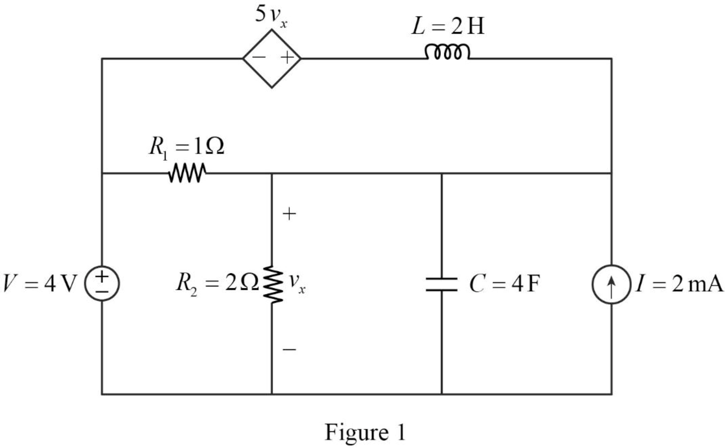
For a DC circuit, at steady state condition, the capacitor acts like open circuit and the inductor acts like short circuit.
Now, the Figure 1 is reduced as shown in Figure 2.
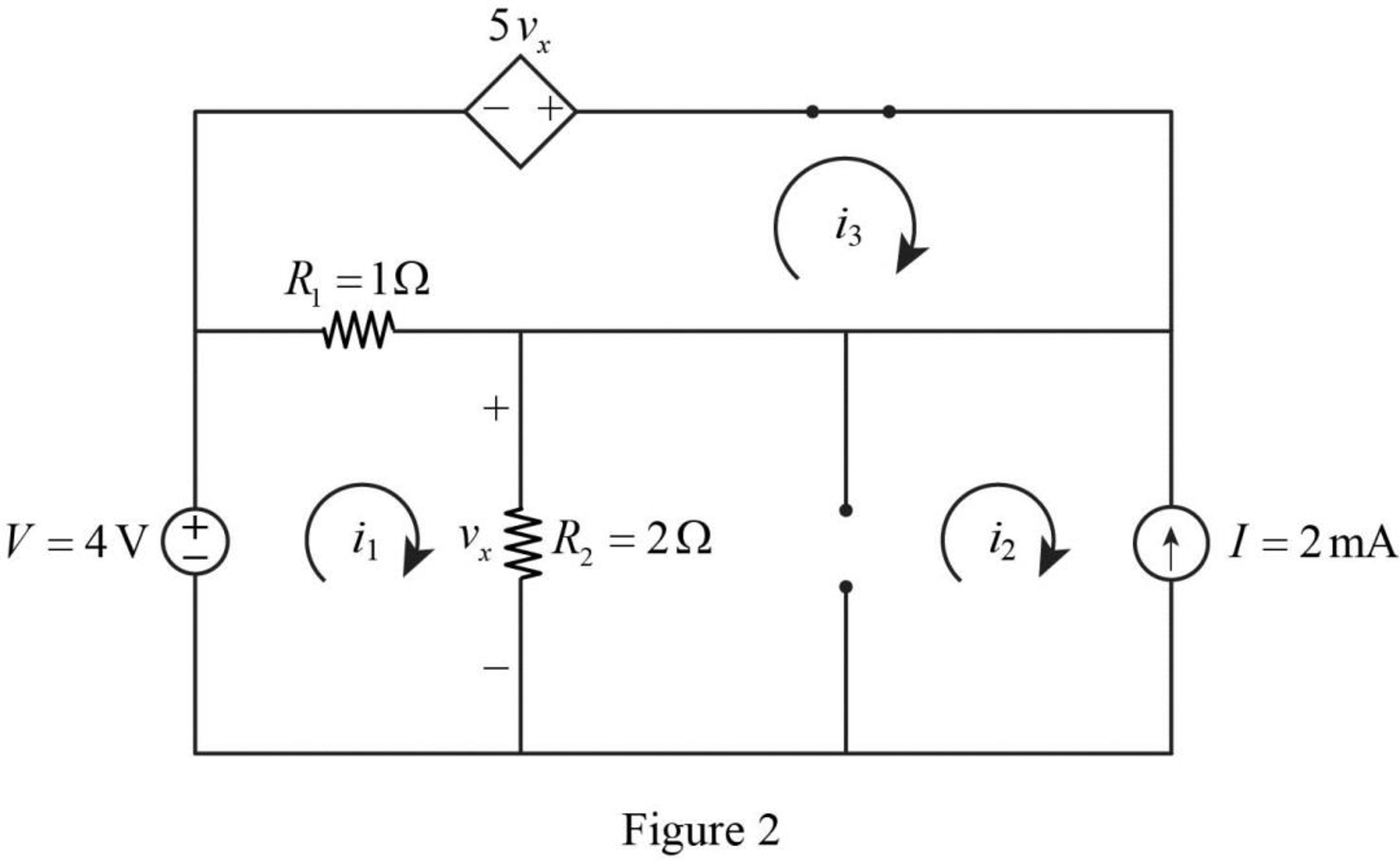
Apply Kirchhoff’s voltage law for loop 1 in Figure 2.
Refer to Figure 2, the current
Substitute
Simplify the above equation to find
Apply Kirchhoff’s voltage law for loop 3 in Figure 2.
Refer to Figure 2, the voltage across the resistor
The voltage
Substitute equation (4) in (3).
Substitute
Substitute equation (2) in (5).
Simplify the above equation to find
Substitute
Refer to Figure 2, the current
Substitute
Refer to Figure 2, the resistor
Write a general expression to calculate the energy stored in a inductor.
Here,
Write a general expression to calculate the energy stored in a capacitor.
Here,
Substitute
Simplify the above equation to find
Substitute
Simplify the above equation to find
Conclusion:
Thus, the value of energy stored in the inductor
(b)
Verify the calculated answers with an appropriate simulation.
(b)
Explanation of Solution
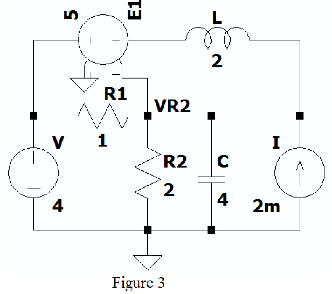
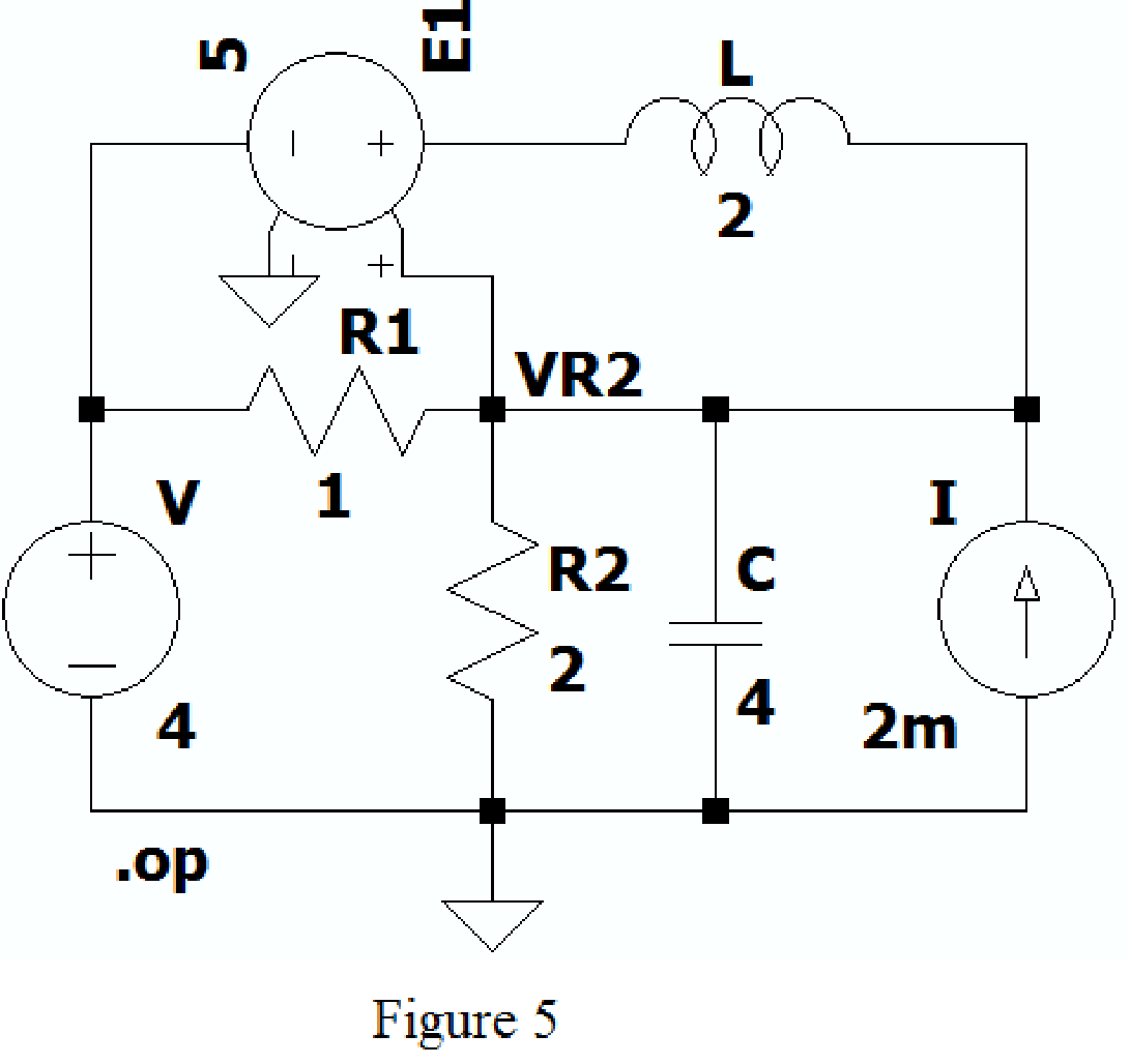
Create the new schematic in LTspice and draw the Figure 1 as shown in Figure 3. Use the Label net option and write VR2 to find voltage across resistor
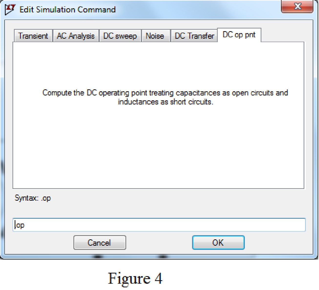
Choose the Dc op point in Edit simulation Cmd as shown in Figure 4.
After adding the above mentioned commands the circuit becomes as shown in Figure 5.
Now run the simulation, the table will be displayed with the values of current through resistors, capacitor and voltage across the capacitor as shown in Figure 6.
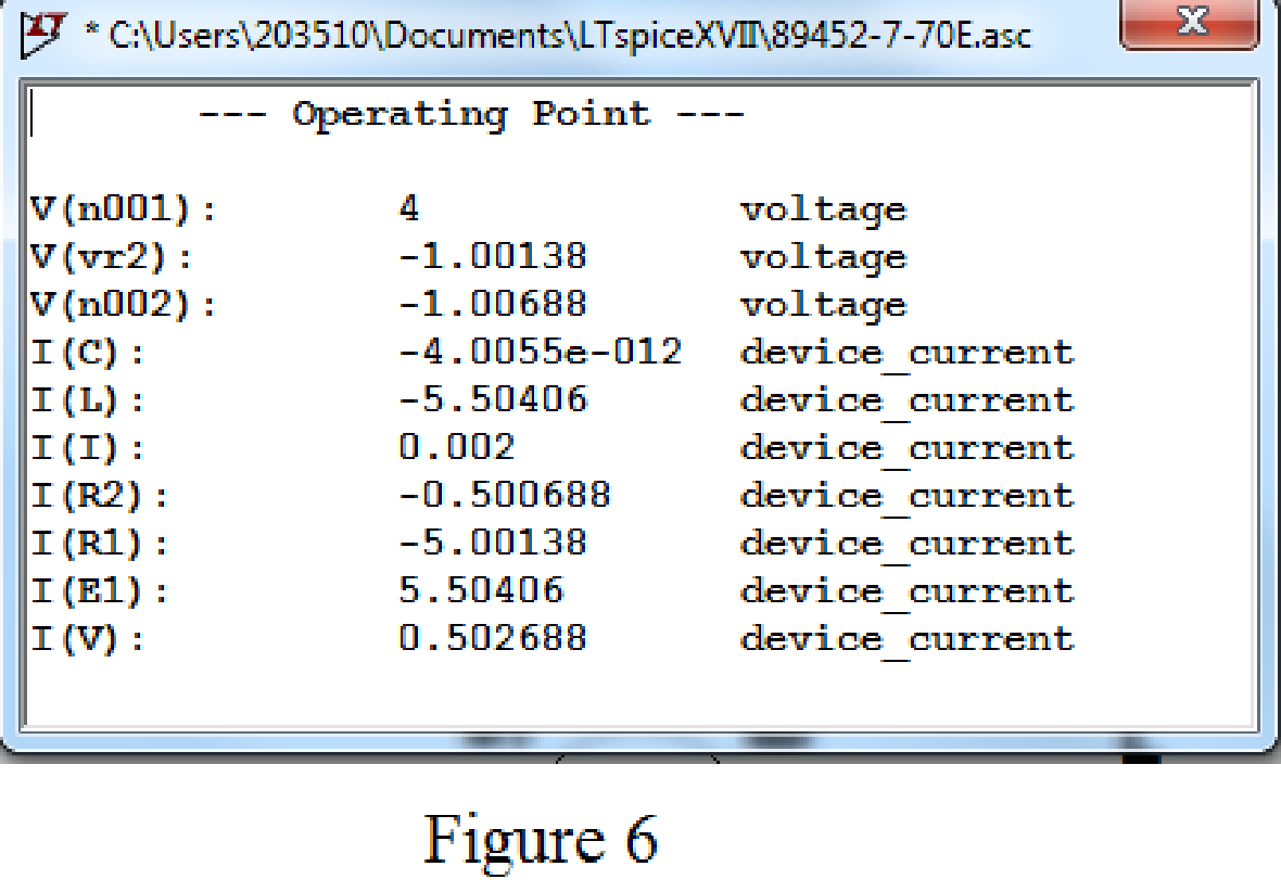
Refer to Figure 6, the value of voltage across the capacitor
Conclusion:
Thus, the calculated answers are verified with an appropriate SPICE simulation.
Want to see more full solutions like this?
Chapter 7 Solutions
Loose Leaf for Engineering Circuit Analysis Format: Loose-leaf


- Determine vo for the circuit shown in Figure 7.98(a) and (b). 12 V Si 22 ka Si 1.8 k2 10 k2 -12 V (a) (b) Figure 7.8arrow_forwardCalculate the power dissipated in the 40 $ resistor and the voltage labeled vc in each of the circuits depicted in Fig. 7.44. 1.2 V 40 Ω M 22 ΩΣ (a) + VC 9.8 mF 1.2 V + VC 9.8 mF 22 Ω (b) 40 Ωarrow_forwardCalculate v₁ and it for each of the circuits depicted in Fig. 7.48, if is = 1 mA and vs 2.1 V. = Vs is + 4.7 ΚΩ M (a) 4.7 ΚΩ. (c) 12 nH iL 12 nH VL is Vs + 4.7 ΚΩ 14 ΚΩ M (b) 4.7 ΚΩ (d) iL 12 nH iL m +51 12 nH 14 ΚΩ ww VL ell +51 VLarrow_forward
- Reduce the circuit depicted in Fig. 7.58 to as few components as possible. 2 V + R W ww R R M FIGURE 7.58 с R + Vx CL ell R мее L Carrow_forwardA 100µF capacitor is connected in series with a 150volt voltmeter that has a resistance of 1,000 ohms per volt. Calculate the reading of the voltmeter at the instant when t equals the time constant following the closing if the switch that impresses 120volts on the circuit.arrow_forwardRp -> sa Figure 7.52 Bia resistance, RGarrow_forward
- Example 7.33. Two coils of inductances 4 and 6 henry are connected in parallel. If their mutual inductance is 3 henry, calculate the equivalent inductance of the combination if (i) mutual inductance assists the self-inductance (ii) mutual inductance opposes the self-inductance.arrow_forwardA circuit comprises an inductor of 9 H of negligible resistance connected in series with a 60 Ω resistor and a 240 V dc source. Determine the following: (a) The time constant in seconds. (b) The current after 1 time constant. (c) Time to develop maximum current in seconds.arrow_forwardMaking the assumption that the circuits in Fig. 7.50 have been connected for a very long time, determine the value for each current labeled ix.arrow_forward
- 4.5 na (1 13 Ω For each circuit shown in Fig. 7.45, calculate the voltage labeled vc. 10 Ω υπ + 10 Ω ΖΩ (α) 3 mF 5Ω 4.5 nA 3 mF = vc M ΖΩ (b) 13 Ω Μ 5 Ωarrow_forwardS0. Although the readings of Fig. 7.99 initially suggest that the network is behaving properly, detemine a possible cause for the undesirable state of the network. 20 V 2.2 k2 330 k2 IDss = 10 mA Vp = -6 V 3.7 V 6.25 V 75 kN 1 k2 FIG. 7.99 Problem 30.arrow_forwardQuestion 11 The current flowing through a 33 mF capacitor is shown graphically in Fig. 7.43. a) Assuming the passive sign convention, sketch the resulting voltage waveform across the device. b) Compute the voltage at 300 ms, 600 ms, and 1.1 s. i(A) 8 4 0 0.2 0.4 0.6 0.8 1.0 1.2 1.4 FIGURE 7.43 1 (S)arrow_forward
 Introductory Circuit Analysis (13th Edition)Electrical EngineeringISBN:9780133923605Author:Robert L. BoylestadPublisher:PEARSON
 Delmar's Standard Textbook Of ElectricityElectrical EngineeringISBN:9781337900348Author:Stephen L. HermanPublisher:Cengage Learning
 Programmable Logic ControllersElectrical EngineeringISBN:9780073373843Author:Frank D. PetruzellaPublisher:McGraw-Hill Education
 Fundamentals of Electric CircuitsElectrical EngineeringISBN:9780078028229Author:Charles K Alexander, Matthew SadikuPublisher:McGraw-Hill Education
 Electric Circuits. (11th Edition)Electrical EngineeringISBN:9780134746968Author:James W. Nilsson, Susan RiedelPublisher:PEARSON
 Engineering ElectromagneticsElectrical EngineeringISBN:9780078028151Author:Hayt, William H. (william Hart), Jr, BUCK, John A.Publisher:Mcgraw-hill Education,