
Videos
The transistor current gain
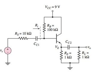
Figure P6.52
A.
The range in the dc values of
Answer to Problem 6.52P
Range of emitter current
and range of emitter current
Explanation of Solution
Given:
Range of transistor current gain
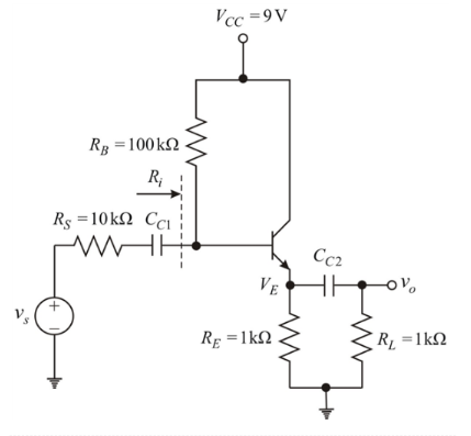
The circuit is given below:

From above circuit, considering BJT s single node, then by KCL, Quiescent emitter current
In CE mode,
From equation (1) and (2),
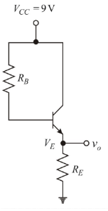
Now, DC analysis of the given circuit:
Reduce source Vs to zero and open the capacitor as shown below:
For
Applying KCL in the base-emitter loop to determine
From equation (3)
Using equation (5) give,
From dc analysis of the circuit, the emitter voltage is,
For
From equation (4)
From equation (3)
Using equation (6) give,
From dc analysis of the circuit, the emitter voltage is,
So, final range of emitter current
and final range of emitter current
B.
Range in the values of input resistance
Answer to Problem 6.52P
Final range of input resistance
and final range of input resistance
Explanation of Solution
Given:
Range of transistor current gain
The circuit is given below:
For
From equation (2)
Now, small signal analysis of the given circuit:
Reduce dc voltage sources to zero, dc current source to open and capacitors to short.
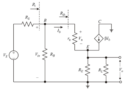
Diffusion resistance
Input resistance
Input resistance
For
From equation (2)
Diffusion resistance
Input resistance
Input resistance
So, final range of input resistance
For
Small signal voltage gain
For
Small signal voltage gain
So, final range of input resistance
Want to see more full solutions like this?
Chapter 6 Solutions
Microelectronics: Circuit Analysis and Design


- Using your own words and without any formula, explain: a- How we deal with the capacitors and DC voltage source when we conduct the AC analysis of an amplifier b- What is the meaning of having a negative voltage gain (for example Av= -20 )[arrow_forwardA circuit is built around a bi-polar NPN transisor. The base network has a diode and a capacitor in series while the collector is connected to the power supply through a resistor. if the resistor is connected to ground; i) draw the circuit ii) provide all the masking layout of the circuitarrow_forward4. A certain common-emitter amplifier has a voltage gain of 100. If the emitter bypass capacitor is removed, (a) The circuit will become un stable (c) The voltage gain will increase (b) the voltage gain will decrease (d) the Q-point will shift 5. For a common-collector amplifier, RE =1002, r'e= 10 2, and Bac=150. The ac input resistance at the base is: (a) 1500 2 (b) 15 k2 (c) 110 Q (d) 16.5 k2 6. If a 10 mV signal is applied to the base of the emitter-follower circuit in Question 5, the output signal is approximately (a) 100 mV (b) 150 mV (c) 1.5 V (d) 10 mVarrow_forward
- Derive the transfer function of the electric circuits for figurearrow_forwardQUESTION 4 In this voltage divider bias circuit, the input is at the base. Output is at the emitter with a high input resistance and low output resistance. The maximum voltage gain is 1 and the coupling capacitors must have a negligible reactance at the frequency of operation. (use to answer a and b) a. Derive the expression for the voltage gain, current gain, and power gain in terms of power delivered to the load, RL. b. Sketch both the DC and AC equivalent circuits. c. Derive the expression for ripple factor of Half Wave Rectification with a capacitor filter.arrow_forwardc) When considering thyristor switching why is Isolated Gate Control needed ? d) The filtered rectifier output is now feeds the regulator circuit shown in figure Q6b. i) Name the type of regulator shown in the shaded area and briefly describe its operation. ii) If the voltage, VL, that appears across the potential divider is regulated to 5V what size zener diode is used? The entire circuit uses the op-amp comparator to iii) allow the limit on the maximum load current to be varied. Explain the operation of the circuit and identify the maximum load current, IL , allowed if the potentiometer's output is 4V and Rx is 20 ?arrow_forward
- Figure 4 shows the amplifier circuit with a voltage divider. Find etc ,VC, and, VCEQ,IBQ,ICQ,IEQ ,Av values by analyzing the DC of the circuit.arrow_forward1. For the following circuit assume re = 30.6 1 a. Draw the small signal equivalent circuit. b. Find the input impedance. c. Find output impedance. d. Find the voltage gain. e. Find the current gain. 4.72 10Farrow_forwardQ6. a. A certain type of temperature transducer, designed to measure temperatures in the range 0-100C°, consists of a thermistor. The thermistor has a nominal resistance of 1400 and forms one arm of a DC bridge circuit, with the other three arms each having a resistance of 14022. The bridge output is measured by an instrument whose input impedance can be assumed infinite. If, in order to limit heating effects, the maximum permissible gauge current is 40 mA, calculate the maximum permissible bridge excitation voltage. If the sensitivity of the thermistor is 340m2/C° and the maximum bridge excitation voltage is used, calculate the bridge output voltage when measuring a pressure of 50 degree Celsius.arrow_forward
- VR2 (t) voltage will be calculated by analyzing the circuit in Figure 1, which includes a non-linear element, with the Small Signal Analysis method. For this purpose a) The operating point of the non-linear element will be found at VkQ, IkQ voltage and current.b) Linearize the nonlinear element at the operating point.c) Find the voltage VR2 (t) by calculating the effect of the variable source using the linear model. β=5 and α=5arrow_forwardIn the small-signal equivalent circuit, the DC voltage source is replaced by a short circuit. Select one: O True O False Consider the circuit shown in the figure belowarrow_forwardDesign a voltage to current converter amplifier. Assume that you have 5v input voltage to the non-inverting input with a frequency of 60hz and another input voltage to the inverting input with a frequency of 60hz, place it before the input resistance. What should be the value of your voltage input in inverting input and input resistance to get a reading of 38.22mA at exactly 22.20ms and what is the shape waveform of the current? What is the value of Vin?Vin = ____ voltsarrow_forward
 Introductory Circuit Analysis (13th Edition)Electrical EngineeringISBN:9780133923605Author:Robert L. BoylestadPublisher:PEARSON
 Delmar's Standard Textbook Of ElectricityElectrical EngineeringISBN:9781337900348Author:Stephen L. HermanPublisher:Cengage Learning
 Programmable Logic ControllersElectrical EngineeringISBN:9780073373843Author:Frank D. PetruzellaPublisher:McGraw-Hill Education
 Fundamentals of Electric CircuitsElectrical EngineeringISBN:9780078028229Author:Charles K Alexander, Matthew SadikuPublisher:McGraw-Hill Education
 Electric Circuits. (11th Edition)Electrical EngineeringISBN:9780134746968Author:James W. Nilsson, Susan RiedelPublisher:PEARSON
 Engineering ElectromagneticsElectrical EngineeringISBN:9780078028151Author:Hayt, William H. (william Hart), Jr, BUCK, John A.Publisher:Mcgraw-hill Education,