
Concept explainers
Videos
Derive the expression for
Answer to Problem 55E
The derived expression for
Explanation of Solution
Calculation:
The redrawn circuit is shown in Figure 1 as follows.
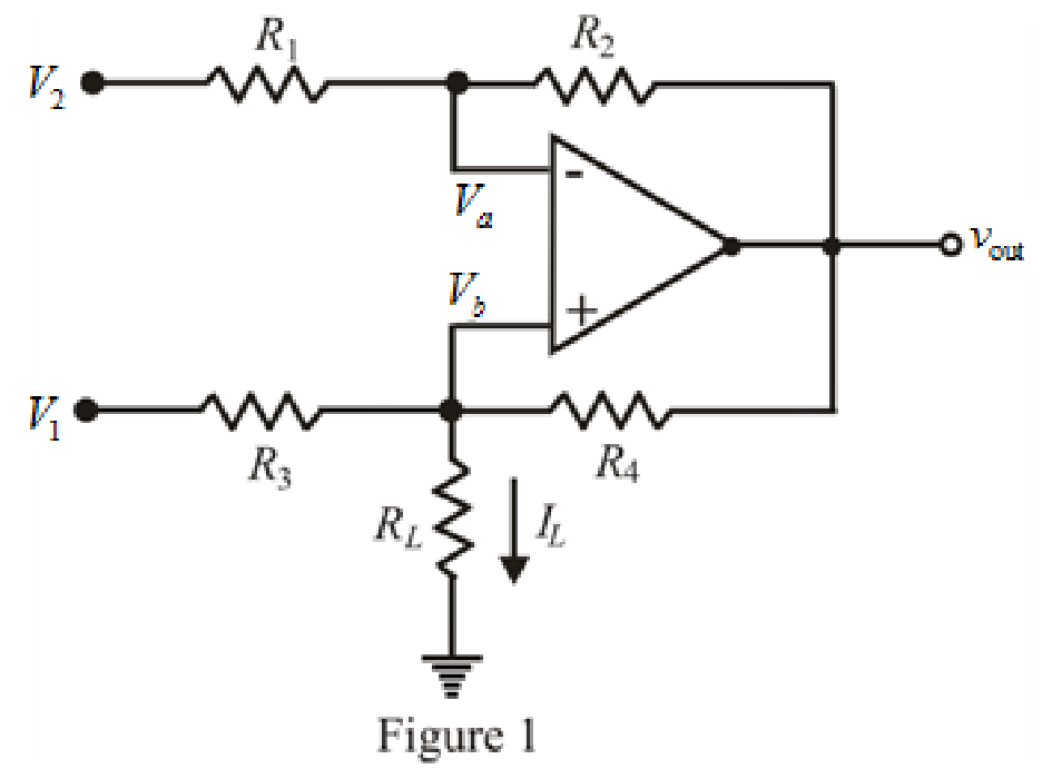
Refer to the Figure 1.
The expression for nodal analysis at node voltage
Here,
The expression for nodal analysis at node voltage
Here,
The expression for the virtual ground concept is as follows.
The expression for current
Here,
Simplify equation (1) for
Simplify equation (2) as follows.
Substitute
Rearrange for
Simplify for
Substitute
Substitute value of
Conclusion:
Thus, the derived expression for
Want to see more full solutions like this?
Chapter 6 Solutions
Loose Leaf for Engineering Circuit Analysis Format: Loose-leaf


- Derive an expression for the output voltage of the circuit in Fig. 6.22 in terms of the four input voltages. Simplify your result as much as possible.arrow_forward*6.42 In the circuit shown in Fig. P6.42, current source / is 1.1 mA, and at 25°C vBE = 680 mV at ig =1 mA. At 25°C with B = 100, what currents flow in RỊ and R2? What voltage would you expect at node E? Noting that the temperature coefficient of vgg for Ig constant is –2 mV/°C, what is the TC of vg? For an ambient temperature of 75°C, what voltage would you expect at node E? Clearly state any simplifying assumptions you make. R2 68 kn R, 6.8 kf 어 Figure P6.42arrow_forwardIn the circuit shown in Fig. P6.42, current source I is 1.1 mA, and at 25°C vBE= 680 mV at iE= 1 mA. At 25°C with B=100, what currents flow in R1 and R2? R₂ 68 ΚΩ R₁ 6.8 k www ww +1₁ OEarrow_forward
- When a switch is closed in a cirvuit containing a battery E,a resistance R and an inductance L,the current i build up at rate given by L di/dt +Ri=E.find "i" as a function "t"arrow_forward*6.68 For the circuit in Fig. P6.68, find V, and V for v, = 0V, +2 V, -2.5 V, and -5 V. The BJTS have B=50. +2.5 V 10 k2 OVE Q2 3 1 kn VB - 2.5 Varrow_forwardOne can assemble a “virtual” solar cell array by using playing cards, or business or index cards, to represent a solar cell. Combinations of these cards in series and/or parallel can model the required array output. a) Assume each card has an output of 0.5 V and a current (under bright light) of 2 A. Using your cards, how would you arrange them to produce an output of 6 A at 3 V (i.e. - 18 W)? b) Suppose you were told that you needed only 18 W (but no required voltage). Would you need more cards to make this arrangement?arrow_forward
- 10. Consider in Figure 6.43 the design of a T-network that transforms a 50 N load impedance to 5 N: jX jX2 5Ω - jX3 50 Ω Figure 6.43: T-network transforming 50 N load impedance to 5 N. Design a T-network with a Q of 6. Find the solution with X1 > 0 and X2 < 0. Specify X1, X2 and X3 to the nearest ohm.arrow_forward6.65 Design the circuit in Fig. P6.65 to obtain I = 0.2 mA, VE = +2 V, and Ve = +5 V. Design for I = 0.l mA. Use standard 5% resistors (refer to Table J.1 in Appendix J). The transistor has VBE = 0.7 V and B = 100. %3D %3D %3D +9 V Rc RB1 RE RB2 Figure P6.65arrow_forwardA 1) Consider the circuit at right, consisting of two LEDS (one red, one green), which you can model as “practical diodes" with VD= 2.0V (LEDS typically have larger VD's than ordinary Si or Ge diodes). R red green B a) If terminals A and B were connected to a DC source with voltage Vo, what would happen? (Consider applying in both polarities, i.e. +Vo and –Vo, and when VoVD...) b) If the terminals A and B were connected to an AC source with peak voltage VO, what would happen? (Consider both very low frequency: f<~1 Hz – and high-frequency cases.) c) If R = 1 k2, and both diodes have a maximum continuous power dissipation of 0.1 W and a peak inverse voltage VPIV = 20V, what is the maximum DC voltage VDCmax which can be safely applied between A and B?arrow_forward
- (d) 1:n V LM C V. e 6.5 A nonideal flyback converter. The flyback converter shown in Fig. 6.32d operates in the continuous conduction mode. The MOSFET has on-resistance Ron, and the diode has a constant forward voltage drop Vp. The flyback transformer has primary winding resistance R, and secondary winding resistance R,. (a) Derive a complete steady-state equivalent circuit model, which is valid in the contin- uous conduction mode, and which correctly models the loss elements listed above as well as the converter input and output ports. Sketch your equivalent circuit. (b) Derive an analytical expression for the converter efficiency. + rele +arrow_forwardOne can assemble a “virtual” solar cell array by using playing cards, or business or index cards, to represent a solar cell. Combinations of these cards in series and/or parallel can model the required array output. Assume each card has an output of 0.5 V and a current (under bright light) of 2 A. Using your cards, how would you arrange them to produce an output of 6 A at 3 V (18 W)?Suppose you were told that you needed only 18 W (but no required voltage). Would you need more cards to make thisarrangement?arrow_forward1) Design a network to maintain a continuous 15 V DC voltage to a machinary having a load impedance of RL = 1,5 kQ. In order to realize this request, a transformer having a primer voltage 220 V AC and a seconder voltage 30 V AC (220/30 V AC transformer), some silicon diodes, zener diode and some resistors of 200 2 can be considered in design. a) Draw the overall network, explain the tasks of each component and overall operation of the network in your design. b) Calculate load current (I1.). c) Calculate power dissipated by zener diode (if used in design)arrow_forward
 Introductory Circuit Analysis (13th Edition)Electrical EngineeringISBN:9780133923605Author:Robert L. BoylestadPublisher:PEARSON
 Delmar's Standard Textbook Of ElectricityElectrical EngineeringISBN:9781337900348Author:Stephen L. HermanPublisher:Cengage Learning
 Programmable Logic ControllersElectrical EngineeringISBN:9780073373843Author:Frank D. PetruzellaPublisher:McGraw-Hill Education
 Fundamentals of Electric CircuitsElectrical EngineeringISBN:9780078028229Author:Charles K Alexander, Matthew SadikuPublisher:McGraw-Hill Education
 Electric Circuits. (11th Edition)Electrical EngineeringISBN:9780134746968Author:James W. Nilsson, Susan RiedelPublisher:PEARSON
 Engineering ElectromagneticsElectrical EngineeringISBN:9780078028151Author:Hayt, William H. (william Hart), Jr, BUCK, John A.Publisher:Mcgraw-hill Education,