The rather simple circuit shown below is known as a voltage divider. The symbol consisting of three horizontal lines is represents “ground” and can be defined as the point where the potential is zero. The voltage divider is widely used in circuits and a single voltage source can be used to provide reduced voltage to a load resistor as shown in the second part of the figure, (a) What is the output voltage V o u t of circuit (a) in terms of R 1 , R 2 , a n d V i n (b) What is the output voltage V o u t of circuit (b) in terms of R 1 , R 2 , R L a n d V i n
The rather simple circuit shown below is known as a voltage divider. The symbol consisting of three horizontal lines is represents “ground” and can be defined as the point where the potential is zero. The voltage divider is widely used in circuits and a single voltage source can be used to provide reduced voltage to a load resistor as shown in the second part of the figure, (a) What is the output voltage V o u t of circuit (a) in terms of R 1 , R 2 , a n d V i n (b) What is the output voltage V o u t of circuit (b) in terms of R 1 , R 2 , R L a n d V i n
The rather simple circuit shown below is known as a voltage divider. The symbol consisting of three horizontal lines is represents “ground” and can be defined as the point where the potential is zero. The voltage divider is widely used in circuits and a single voltage source can be used to provide reduced voltage to a load resistor as shown in the second part of the figure, (a) What is the output voltage Vout of circuit (a) in terms of
R
1
,
R
2
,
a
n
d
V
i
n
(b) What is the output voltage Vout of circuit (b) in terms of
The figure below shows a voltage divider, a circuit used to obtain a desired voltage AVout from a source voltage E.
R1
R2
AVout
Determine the required value of R, if E = 6.24 V, AV out = 1.77 V, and R, = 2.03 x 10° n.
HINT
For the circuit shown in figure below, the capacitors were each discharged before beingconnected to the voltage source. Find,(a) the equivalent capacitance(Ceq) of the combination.(b) the voltage across each capacitor(i.e.V1=?,V2=?V3=?).
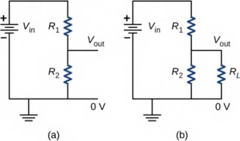
72. The rather simple circuit shown below is known as a
voltage divider. The symbol consisting of three horizontal
lines is represents "ground" and can be defined as the point
where the potential is zero. The voltage divider is widely
used in circuits and a single voltage source can be used
to provide reduced voltage to a load resistor as shown
in the second part of the figure. (a) What is the output
voltage Vout of circuit (a) in terms of R1, R2, and Vin?
(b) What is the output voltage Vout of circuit (b) in terms
of R1, R2, RL, and Vin ?
R1
Vin R1
in
Vout
Vout
R2
R2
RL
OV
O V
(a)
(b)
Need a deep-dive on the concept behind this application? Look no further. Learn more about this topic, physics and related others by exploring similar questions and additional content below.
How To Solve Any Resistors In Series and Parallel Combination Circuit Problems in Physics; Author: The Organic Chemistry Tutor;https://www.youtube.com/watch?v=eFlJy0cPbsY;License: Standard YouTube License, CC-BY


 Physics for Scientists and Engineers: Foundations...PhysicsISBN:9781133939146Author:Katz, Debora M.Publisher:Cengage Learning
 Principles of Physics: A Calculus-Based TextPhysicsISBN:9781133104261Author:Raymond A. Serway, John W. JewettPublisher:Cengage Learning