
Concept explainers
The Laplace transform of the given periodic function.
Answer to Problem 1P
The Laplace transform of the given periodic function is
Explanation of Solution
Given data:
The given periodic waveform is shown in Figure 1.
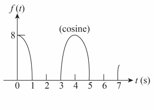
The time period of this waveform is
Calculation:
The function expression calculated from the figure is written as,
Here,
The angular frequency is given by,
Substitute
Substitute
The Laplace transform of a periodic signal is written as,
The Laplace transform of the function
Substitute
The general form of
Substitute
Substitute
The above equation is divided into two parts as,
The first part
The second part
Solve for
Solve further as,
Solve further as,
Solve equation (6) for
Solve further as,
Solve further as,
Substitute
The Laplace transform of
Substitute
Substitute
Substitute
Substitute
Conclusion:
Therefore, the Laplace transform of the given periodic function is.
Want to see more full solutions like this?
Chapter A7 Solutions
Loose Leaf for Engineering Circuit Analysis Format: Loose-leaf


- H.W: Find the output of the following system (plot the waveforms) 1) System g(t) f(t) h(t) h(t) 3 + -1 +1 3 2) System f(1) g(t). h(t) 4 h(t) 1 -2 1 2arrow_forward(X) find (Convolution two signals. AfCH) and Ypg (+) Correlation of the Ag(t) t-1 followingarrow_forwardDraw the following expressions as time domain graphs.arrow_forward
- Determine which differential equation best represents the system described by the block diagram below. x(t) O a. O b. O C. O d. + y(t) - 3. y(t) + 3 dy(t) dt y(t) - 3 3 dy(t) dt d dt = d dt dy(t) -4x(t) + 2- dt y(t) + 3 dy(t) — 4x(t) + 2 d²x(t) dt² -4 2 d²x(t) dt² = -4x(t) + 2- 4x(t) + 2- d²r(t) dt² d²r(t) dt² = 0 = 0 ) y(t), +arrow_forwardFind the Laplace transform of the waveform shown. aarrow_forwardDetermine the laplace toansform of peniodic function shown in the given figuse. ft) sec) 8.arrow_forward
- For each of the three circuit elements shown in the time domain, draw the s-domain representation: ig(t) i(t) ic(t) BVR(t) + G v₁(t) vc(t)arrow_forwardDetermine which differential equation best represents the system described by the block diagram below. x(t) O a. b. C. d. + y(t) - 3 dy() dt y(t)+3° y(t) — 3. dy(t) dt dy(t) dt y(t) + 3 dy(t) dt 3 d dt d dt ¸d²x(t) dt² · 4x(t) + 2· -4 = −4x(t) + 2- = = −4x(t) + 2- 2 d²x(t) dt² d²x(t) dt² = 0 - 4x(t) + 2² = 0 d²x(t) dt² + y(t)arrow_forwardFind damping ratio 2 and natural frequency wn for the functionarrow_forward
- b) Given the following block diagram r(t) 1/m D- K₂ H S c(t) derive the differential equation relating the output c(t) to the input r(t) warrow_forwardInverse laplace using partial fraction decompositionarrow_forwardc) Solve the circuit in the time domain Apply the differential equation technique to find i(t) for t>0 in the circuit shown in the figure and obtain the graph of the response including the interval immediately before the movement of the switch. 12 V 6 kfl ww AWAY 1-0 0.2 mH (10) 4 kf 02 Aarrow_forward
 Introductory Circuit Analysis (13th Edition)Electrical EngineeringISBN:9780133923605Author:Robert L. BoylestadPublisher:PEARSON
 Delmar's Standard Textbook Of ElectricityElectrical EngineeringISBN:9781337900348Author:Stephen L. HermanPublisher:Cengage Learning
 Programmable Logic ControllersElectrical EngineeringISBN:9780073373843Author:Frank D. PetruzellaPublisher:McGraw-Hill Education
 Fundamentals of Electric CircuitsElectrical EngineeringISBN:9780078028229Author:Charles K Alexander, Matthew SadikuPublisher:McGraw-Hill Education
 Electric Circuits. (11th Edition)Electrical EngineeringISBN:9780134746968Author:James W. Nilsson, Susan RiedelPublisher:PEARSON
 Engineering ElectromagneticsElectrical EngineeringISBN:9780078028151Author:Hayt, William H. (william Hart), Jr, BUCK, John A.Publisher:Mcgraw-hill Education,