
Videos
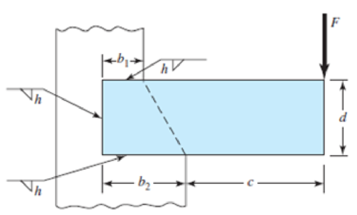
9-30 to 9-31 A steel bar of thickness h is subjected to a bending force F. The vertical support is stepped such that the horizontal welds are b1 and b2 long. Determine F if the maximum allowable shear stress is τallow.
| Problem Number | b1 | b2 | c | d | h | τallow |
| 9–30 | 2 in | 4 in | 6 in | 4 in |
|
25 kpsi |
| 9–31 | 30 mm | 50 mm | 150 mm | 50 mm | 5 mm | 140 MPa |
Problems 9–30 to 9–31
The bending force
Answer to Problem 31P
The bending force
Explanation of Solution
The below figure shows the dimension of the weld.
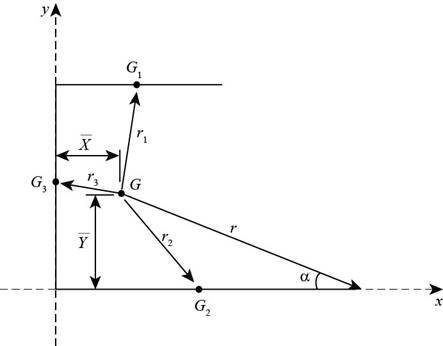
Figure-(1)
Write the expression for throat area of weld-1.
Here, the thickness of weld is
Write the expression for throat area of weld-2.
Here, the length of weld is
Write the expression for throat area of weld-3.
Here, the length of weld is
Write the expression for total throat area.
Write the expression for total length of the weld.
Write the expression for location of centroid along x-direction.
Here, the centroidal length of weld-1 is
Write the expression for centroid along y-direction.
Here, the centroidal distance of weld-1 is
Write the expression for the length between total weld and weld-1.
Write the expression for length between total weld and weld-2.
Write the expression for length of total weld and weld-3.
Write the expression for polar moment of inertia of weld-1 about its centroid.
Write the expression for moment of inertia of weld-2 about its centroid.
Write the expression for polar moment of inertia of weld-3 about its centroid.
Write the expression for polar moment of inertia of the total weld.
Write the expression for length where maximum secondary shear stress occurs.
Write the expression for angle of
Write the expression for moment about weld center.
Here, the load on the weld is
Write the expression for primary shear stress.
Write the expression for secondary shear.
Write the expression for maximum shear stresss.
Conclusion:
Substitute
Substitute
Substitute
Substitute
Substitute
Substitute
Substitute
Substitute
Substitute
Substitute
Substitute
Substitute
Substitute
Substitute
Substitute
Substitute
Substitute
Substitute
Substitute
Substitute
Thus, the bending force is
Want to see more full solutions like this?
Chapter 9 Solutions
Shigley's Mechanical Engineering Design (McGraw-Hill Series in Mechanical Engineering)


- Determine the length of the fillet weld lap joint shown in the figure below. The weld has to resist a tension of 115 kips. The effective throat for the weld h = 0.5 inches, and the allowable stress is 21 ksi. length → F = 115 kips harrow_forwardThe steel shafts are connected together using a fillet weld as shown in the figure below. (Figure 1) 12 mm T=60 N-m 12 mm 50 mm- 12 mm 1 12 mm Determine the average shear stress in the weld along section a-s if the torque applied to the shafts is T = 63 N-m. Note: The critical section where the weld fails is along section a-a.arrow_forwardQ1: The weldment shown in the figure is subjected to a force F. The hot-rolled steel bar has a thickness h and is of AISI 1040 steel. The vertical support is likewise AISI 1040 HR steel. The electrode is given in the table below. Estimate the static load F the bar can carry if two fillet welds are used. b (mm) h (mm) d (mm) 70 Elecrode E8010 30 6 b→→ Farrow_forward
- Q1: The weldment shown in the figure is subjected to a force F. The hot-rolled steel bar has a thickness h and is of AISI 1040 steel. The vertical support is likewise AISI 1040 HR steel. The electrode is given in the table below. Estimate the static load F the bar can carry if two fillet welds are used. b (mm) h (mm) d (mm) 70 Elecrode E8010 30 4arrow_forward1. The welded joint shown below is subjected to a 40 kN of static axial and a 40 kN of static bending loads (F and F1) as shown below. The materials are made of steel with Sut-2070 MPa and Sy=1830MPA. Calculate the factor of safety of the weld. Where, h-6 mm, b-30 mm, c=100 mm d-60 mm, and both forces are equal and each 40 kN (F=F1=40 kN). F F1 d State the reason of your selection in your answer but use only 2 sentences (maximum of 2 lines!) for each answer. 2) Suggest the most suitable bearing type with quantity if a shaft rotates at a speed of 1500 rev/min, subjected to mid-range radial load in a limited radial space. 3) Suggest the most suitable bearing type with quantity if maximum stiffness, stability and resistance to shaft misalignment are desired at a shaft, rotating at 1000 rev/min, under a light radial load. In addition, the shaft is subjected to comparably light thrust loads from either directions. 4) Suggest the most suitable spring type for the following application…arrow_forwardQ1: The weldment shown in the figure is subjected to a force F. The hot-rolled steel bar has a thickness and is of AISI 1040 steel. The vertical support is likewise AISI 1040 HR steel. The electrode is given in the table below. Estimate the static load F the bar can carry if two fillet welds are used. h (mm) b (mm) 30 d (mm) 70 Elecrode E8010arrow_forward
- A beam 1m long with dimensions b = 50 mm and d = 100 mm is subjected to a load of 500 kgs as shown. A 7018 electrode is used to weld the beam section all around. Weld size is 12 mm. Approximate the maximum stress in the weld. Compare the maximum weld stress with the strength of the electrode. F 12 -Xarrow_forwardThe figure below shows two plates connected by two rivets. The plates are made from aluminum 6061-T6 and the rivets are made from aluminum 2014-T4. Evaluate the maximum allowable force on the connection to meet the following design criteria: (a) The shear stress in a rivet cannot exceed 14 of the ultimate strength in shear. (b) The tensile stress in the plates cannot exceed 13 of the yield strength. (c) The bearing stress on either the plates or the rivets cannot exceed the design bearing stress 9 mm 75 mm 38 mm 38 mm 12 mm dia. 9 mmarrow_forwardQ1: The weldment shown in the figure is subjected to a force F. The hot-rolled steel bar has a thickness h and is of AISI 1040 steel. The vertical support is likewise AISI 1040 HR steel. The electrode is given in the table below. Estimate the static load F the bar can carry if two fillet welds are used. d (mm) h (mm) Elecrode b (mm) 30 70 6 E8010 4 ko →arrow_forward
- Ql: The steel strap with thickness of 12 mm is to be welded to a rigid frame to carry a static load of F=20 kN. The strap and frame are welded together by fillet welds along two sides. Using the maximum distortion energy theory, determine the minimum length of the weld to be on safe side. The yield strength is 420 MPa. The safety factor should be considered as 4. (k=12 mm)arrow_forwardSituation 2: The lap splice shown will develop a full strength as shown in the figure. Using E70 electrodes. The width of the plate is 150 mm and the thickness is 10 mm. Use Fy = 248 MPa T4 46 mm 48 mm 1. Which of the following nearly gives the diameter of the slot weld using the LRFD method. O 45 mm T O 47 mm T Warrow_forwardTwo bars are connected with a welded butt joint as shown. The bar dimensions are b = 200 mm and t = 50 mm, and the angle of the weld is a = 45°. The bars transmit a force of P = 301 kN. What is the magnitude of the average shear stress that acts on plane AB? Weld В P A Answer: T= i MPаarrow_forward
 Elements Of ElectromagneticsMechanical EngineeringISBN:9780190698614Author:Sadiku, Matthew N. O.Publisher:Oxford University Press
 Mechanics of Materials (10th Edition)Mechanical EngineeringISBN:9780134319650Author:Russell C. HibbelerPublisher:PEARSON
 Thermodynamics: An Engineering ApproachMechanical EngineeringISBN:9781259822674Author:Yunus A. Cengel Dr., Michael A. BolesPublisher:McGraw-Hill Education
 Control Systems EngineeringMechanical EngineeringISBN:9781118170519Author:Norman S. NisePublisher:WILEY
 Mechanics of Materials (MindTap Course List)Mechanical EngineeringISBN:9781337093347Author:Barry J. Goodno, James M. GerePublisher:Cengage Learning
 Engineering Mechanics: StaticsMechanical EngineeringISBN:9781118807330Author:James L. Meriam, L. G. Kraige, J. N. BoltonPublisher:WILEY