
Concept explainers
Videos
|
|
|
|
|
|
||||
|
|
|
|
|
|
||||
|
|
|
|
|
|
||||
|
|
|
|
|
|
||||
|
|
|
|
|
|
||||
|
|
|
|
|
|
||||
|
|
|
|
|
|
||||
|
|
|
|
|
|
||||
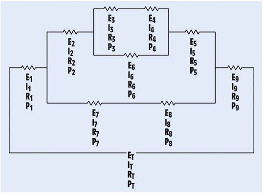
FIGURE 8-26 A combination circuit.
The unknown values in the circuit.
Answer to Problem 8PP
| ET = 24.04 V | E1 = 3.4V | E2 = 4.8 V | E3 = 0.478 V | E4 = 1.248 V |
| IT = 24.02mA | I1 = 24.02mA | I2 = 9.614 mA | I3 = 3.854 mA | I4 = 3.854 mA |
| RT = 942 Ω | R1 = 144 Ω | R2 = 499 Ω | R3 = 124Ω | R4 = 324 Ω |
| PT = 0.576 W | P1 = 0.0806W | P2 = 0.0461W | P3 = 0.00184W | P4 = 0.00481W |
| E5 = 2.11 V | E6 = 1.726V | E7 = 3.6 V | E8 = 5.04V | E9 = 12 V |
| I5 = 9.614 mA | I6 = 5.76 mA | I7 = 14.41 mA | I8 = 14.41 mA | I9 = 24.02 mA |
| R5 = 220 Ω | R6 = 300Ω | R7 = 86Ω | R8 = 360Ω | R9 = 500 Ω |
| P5 = 0.0203 W | P6 = 0.00995 W | P7 = 0.0518W | P8 = 0.0726W | P9 = 0.288 W |
Explanation of Solution
In the given question,
Current flowing through R1 is denoted by I1
Current flowing through R2is denoted by I2
Current flowing through R3 and R4 is denoted by I3(= I4)
Current flowing through R5 is denoted by I5
Current flowing through R6 is denoted by I6
Current flowing through R7 and R8 is denoted by I7 (= I8)
Current flowing through R9is denoted by I9
The total power consumed by the circuit is equal to sum of power consumed by individual resistors. Hence,
Using the voltage E4 and Power P4, we calculate resistance R4 and current I4
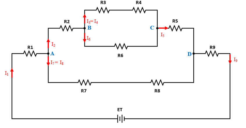
Since R3 and R4 are in series, the same current flows through both. Therefore, I3=I4=3.854 mA
Using the current I3 and resistance R3 find the voltage E3
Since R6 is in parallel with series combination of R3 and R4. Hence,
E6= 0.478 + 1.248 =1.726 V
Using the voltage E6 and Power P6, we calculate resistance R6 and current I6
At node B,
Using P2 and I2, we calculate R2
Using P2 and I2, we calculate E2
Since the incoming current in a network is equal to the outgoing current, current at node B= current at node C: I2=I5=9.614 mA
Using the voltage E5 and Power P5, we calculate resistance R5 and current I5
The total voltage drop across R7 and R8 i.e. E7 and E8 will be
The total power consumed in the branch containing resistors R7 and R8 will be 0.0518+0.0726 = 0.1244 W
Using the total power consumed and the total voltage, we can compute the total current in the network of R7 and R8.
Using the voltage and Power, we calculate R7, R8 and current I7, I8
At node A,
Since the incoming current in a network is equal to the outgoing current, current at node A=current at node D: I1 = I9 =IT=24.02 mA
Using the current I1 and Power P1, we calculate resistance R1 and voltage E1
Using the current I9 and Power P9, we calculate resistance R9 and voltage E9
Total voltage applied across the network will be,
Want to see more full solutions like this?
Chapter 8 Solutions
Delmar's Standard Textbook Of Electricity


- Plz do it byhand. Complete solution plzarrow_forward.EE < 1.13 Calculate the effective resistance between the terminals A and B in the following arrangements. ov 150 C 300 (R E 1.110 B B 2ND 1340 (4) 1.14 Calculate the voltages V1, V2 and V3 in the following arrangements. 9 V (a) 11:33 +44 7440 401120 01/01/2024, 14:37 50 £2 V₁ 100 £2 12 V n (b) 20 Ω 60 2 All Media V₂ 10 V (c) 10 Q2 40 Ω V₂ Eparrow_forward7 need answer asap will give thumbs u parrow_forward
- 22 1852 172 12 52 The circuit shown in Figure has been connected for a long time. What is the potential difference across the 22-2 resistor? O A) 13.5 V O B) 32.4 V C) 72 V O D) 58.5 V E) 39.6 Varrow_forwardNOTE: Solve this as soon as possible, I need this urgently. Determine the currents Iy and I, in the circuit below 6 mA 1.51 1 mAarrow_forwardan infimte long wirer along Z am3 w A chorge density Rs Five È yoint G,0,0)arrow_forward
- Problem 15. A source of e.m.f. of 15 V supplies a current of 2A for six minutes. How much energy is provided in this time?arrow_forwardCalculate the coefficient of linear expansion of the metal rod. Show your solution Metal rod L0 T0 Tf R1 R2 α Copper 60.000cm 28⁰C 100⁰C 60.000 cm 60.073cmarrow_forwardDetermine Io1 0.33 kn D1 D2 10V Si Ge D1 I2 O A. 29.40 mA O B. 14.08 mA O C.0 mA O D. 14.70 mA O E. 14.80 mAarrow_forward
 Introductory Circuit Analysis (13th Edition)Electrical EngineeringISBN:9780133923605Author:Robert L. BoylestadPublisher:PEARSON
 Delmar's Standard Textbook Of ElectricityElectrical EngineeringISBN:9781337900348Author:Stephen L. HermanPublisher:Cengage Learning
 Programmable Logic ControllersElectrical EngineeringISBN:9780073373843Author:Frank D. PetruzellaPublisher:McGraw-Hill Education
 Fundamentals of Electric CircuitsElectrical EngineeringISBN:9780078028229Author:Charles K Alexander, Matthew SadikuPublisher:McGraw-Hill Education
 Electric Circuits. (11th Edition)Electrical EngineeringISBN:9780134746968Author:James W. Nilsson, Susan RiedelPublisher:PEARSON
 Engineering ElectromagneticsElectrical EngineeringISBN:9780078028151Author:Hayt, William H. (william Hart), Jr, BUCK, John A.Publisher:Mcgraw-hill Education,