
International Edition---engineering Mechanics: Statics, 4th Edition
4th Edition
ISBN: 9781305501607
Author: Andrew Pytel And Jaan Kiusalaas
Publisher: CENGAGE L
expand_more
expand_more
format_list_bulleted
Concept explainers
Videos
Textbook Question
Chapter 8, Problem 8.91P
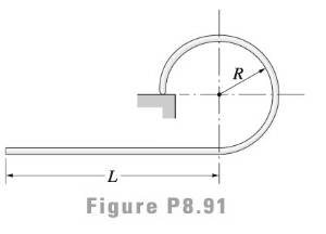
What is the ratio L/R for which the uniform wire figure can be balanced in the position shown?
Expert Solution & Answer
Want to see the full answer?
Check out a sample textbook solution
Students have asked these similar questions
The lengths of various links of a mechanism, as shown in Figure 2, are:
OA = 0.3 m; AB = 1 m; CD = 0.8 m; and AC = CB.
A
45°
В
Figure 2: Slider cranck mechanism
Draw the displacemt diagram to a scale.
Find the angle of contact on the small pulley for a belt drive with center distance of 75 in. if pulley diameters are 9 in. and 18 in., respectively.
Figure below shows a four-bar linkage (non-scaled diagram) at an instant. The input
angle is equal to the output angle (02 - 04) and the transmission angle is 30°. The
input link is extended beyond joint B and an input force (Fin) is applied at the end of
it, while an output force is drawn from the midpoint of the output link. If an output
force of 30 N is desired from an input force of 10 N, how far the input link should be
extended, i.e., what is the distance from point B to the point where Fin is applied.
Fin
B
out
undefined
02
04
A.
Non-scaled diagram; AB = 10, CD=r4 = 30 (output), all in mm
Chapter 8 Solutions
International Edition---engineering Mechanics: Statics, 4th Edition
Ch. 8 - Use integration to determine the coordinates of...Ch. 8 - Use integration to determine the coordinates of...Ch. 8 - Use integration to determine the coordinates of...Ch. 8 - Use integration to determine the coordinates of...Ch. 8 - Use integration to determine the coordinates of...Ch. 8 - Use integration to determine the coordinates of...Ch. 8 - Using integration, locate the centroid of the area...Ch. 8 - Determine the y-coordinate of the centroid of the...Ch. 8 - Determine the y-coordinate 0f the centroid of the...Ch. 8 - Use integration to locate the centroid of the...
Ch. 8 - Locate the centroid of the parabola by...Ch. 8 - Use integration to locate the centroid of the...Ch. 8 - The parametric equations of the plane curve known...Ch. 8 - Use the method of composite areas to calculate the...Ch. 8 - Use the method of composite areas to calculate the...Ch. 8 - Use the method of composite areas to calculate the...Ch. 8 - Use the method of composite areas to calculate the...Ch. 8 - Use the method of composite areas to calculate the...Ch. 8 - Use the method of composite areas to calculate the...Ch. 8 - Use the method of composite areas to calculate the...Ch. 8 - Use the method of composite areas to calculate the...Ch. 8 - The plane region is bounded by a semicircle of...Ch. 8 - The centroid of the plane region shown is at C....Ch. 8 - Compute the centroidal coordinates of the L-shaped...Ch. 8 - Find the centroidal coordinates of the plane...Ch. 8 - Using the method of composite areas, find the...Ch. 8 - Given that the centroid of the plane region is at...Ch. 8 - Using the method of composite curves, locate the...Ch. 8 - Using the method of composite curves, locate the...Ch. 8 - Using the method of composite curves, locate the...Ch. 8 - Using the method of composite curves, locate the...Ch. 8 - Using the method of composite curves, locate the...Ch. 8 - Using the method of composite curves, locate the...Ch. 8 - Determine the ratio a/b for which the centroid of...Ch. 8 - Use numerical integration to locate the centroid...Ch. 8 - Determine the centroidal coordinates of the plane...Ch. 8 - Compute the centroidal y-coordinate of the plane...Ch. 8 - The equation of the catenary shown is y = 100 cosh...Ch. 8 - Use integration to locate the centroid of the...Ch. 8 - By integration, find the centroid of the surface...Ch. 8 - Locate the centroid of the volume obtained by...Ch. 8 - Solve Prob. 8.41 assuming that the triangle is...Ch. 8 - Use integration to find the centroidal coordinates...Ch. 8 - Solve Prob. 8.43 assuming that the area is...Ch. 8 - Verify the centroidal z-coordinate of the pyramid...Ch. 8 - Use integration to compute the z-coordinate of the...Ch. 8 - Determine the centroidal z-coordinate of the...Ch. 8 - Prob. 8.48PCh. 8 - Locate the centroid of the volume between the...Ch. 8 - Prob. 8.50PCh. 8 - Prob. 8.51PCh. 8 - By the method of composite volumes, determine the...Ch. 8 - By the method of composite volumes, determine the...Ch. 8 - By the method of composite volumes, determine the...Ch. 8 - By the method of composite volumes, determine the...Ch. 8 - By the method of composite volumes, determine the...Ch. 8 - By the method of composite volumes, determine the...Ch. 8 - Use the method of composite volumes to determine...Ch. 8 - The cylindrical container will have maximum...Ch. 8 - Using the method of composite surfaces, locate the...Ch. 8 - Using the method of composite surfaces, locate the...Ch. 8 - Using the method of composite surfaces, locate the...Ch. 8 - Using the method of composite surfaces, locate the...Ch. 8 - Using the method of composite surfaces, locate the...Ch. 8 - Using the method of composite surfaces, locate the...Ch. 8 - The picture board and its triangular supporting...Ch. 8 - By the method of composite curves, locate the...Ch. 8 - By the method of composite curves, locate the...Ch. 8 - By the method of composite curves, locate the...Ch. 8 - Use numerical integration to find the centroid of...Ch. 8 - Prob. 8.71PCh. 8 - Locate the centroid of the volume generated by...Ch. 8 - Prob. 8.73PCh. 8 - Prob. 8.74PCh. 8 - Prob. 8.75PCh. 8 - A 6-in. diameter hole is drilled in the conical...Ch. 8 - A torus is formed by rotating the circle about the...Ch. 8 - A solid of revolution is formed by rotating the...Ch. 8 - Compute the volume of the spherical cap that is...Ch. 8 - Calculate the surface area of the truncated sphere...Ch. 8 - The rim of a steel V-belt pulley is formed by...Ch. 8 - Determine the volume of the machine part shown.Ch. 8 - A solid is generated by rotating the plane area...Ch. 8 - Prob. 8.84PCh. 8 - Find the surface area of the 90 duct elbow.Ch. 8 - Determine the volume of the concrete arch dam.Ch. 8 - (a) Find the volume of liquid contained in the...Ch. 8 - Compute the surface area of the axi-symmetric...Ch. 8 - The steel cylinder with a cylindrical hole is...Ch. 8 - The hemispherical glass bowl is filled with water....Ch. 8 - What is the ratio L/R for which the uniform wire...Ch. 8 - Small screws are used to fasten a piece of...Ch. 8 - Prob. 8.93PCh. 8 - 3.94 The aluminum cylinder is attached to the...Ch. 8 - Prob. 8.95PCh. 8 - Prob. 8.96PCh. 8 - Prob. 8.97PCh. 8 - Locate the center of gravity of the hammer if the...Ch. 8 - Prob. 8.99PCh. 8 - The cylindrical water tank with R = 10 ft and H =...Ch. 8 - Prob. 8.101PCh. 8 - Five 34-in. diameter holes are to be drilled in a...Ch. 8 - Wind pressure acting on a cylinder can be...Ch. 8 - Prob. 8.104PCh. 8 - The pressure acting on the square plate varies as...Ch. 8 - Prob. 8.106PCh. 8 - Prob. 8.107PCh. 8 - If the intensity of the line loading is...Ch. 8 - Prob. 8.109PCh. 8 - The intensity of the line loading acting on a...Ch. 8 - Determine the resultant force or resultant couple...Ch. 8 - The inside surface of each thin shell carries a...Ch. 8 - Calculate the resultant force caused by the water...Ch. 8 - Determine the resultant force acting on the elbow...Ch. 8 - Determine the smallest distance I) that would...Ch. 8 - Each of the three gates has a constant width 1:...Ch. 8 - The concrete dam shown in cross section holds back...Ch. 8 - A concrete seawater dam is shown in cross section....Ch. 8 - Determine the force F required to pull up the...Ch. 8 - The normal pressure acting on the triangular plate...Ch. 8 - One side of the container has a 03-m square door...Ch. 8 - The 12-ft wide quarter-circular gate AB is hinged...Ch. 8 - The center of gravity of the plane wire figure is...Ch. 8 - The 10-m wide gate restrains water at a depth of 6...Ch. 8 - Find the resultant of the line load shown.Ch. 8 - Prob. 8.126RPCh. 8 - Determine the centroidal coordinates of the volume...Ch. 8 - Prob. 8.128RPCh. 8 - Prob. 8.129RPCh. 8 - Prob. 8.130RPCh. 8 - Using the method of composite areas, find the...Ch. 8 - Find the centroid of the truncated parabolic...Ch. 8 - Prob. 8.133RPCh. 8 - A solid of revolution is formed by rotating the...Ch. 8 - Two hemispherical shells of inner diameter 1 m are...Ch. 8 - Calculate the area of the surface generated when...Ch. 8 - Determine the resultant of the line loading, given...Ch. 8 - Determine the centroidal coordinates of the plane...Ch. 8 - The sheet metal trough has a uniform wall...Ch. 8 - The trough is filled with water (=62.4lb/ft3)....Ch. 8 - The thin-walled cylindrical can with a spherical...Ch. 8 - Find the location of the centroid of the shaded...
Knowledge Booster


Learn more about
Need a deep-dive on the concept behind this application? Look no further. Learn more about this topic, mechanical-engineering and related others by exploring similar questions and additional content below.Similar questions
- Qestion-1: A slider-crank mechanism is shown in figure below. Position vectors for various linkages are drawn as shown in figure. Length of the rotating Link-1 (L1) is continuously changing due to the slider placed on it. Link-3 is fixed and aligned along y-axis. Note: All angles are measured anti-clockwise from x-axis and Link-1 is rotating with uniform velocity Take: L2 = 20mm, 02 =45°, L3= 30mm, o=10rad/sec, V2= 1000mm/s. a) Formulate the vector loop, position, velocity and acceleration equations b) Solve to find 01, L1, linear velocity of slider and angular acceleration of link-1. c) Identify if the mechanism can be declared as spatial or planar mechanism also identify total number of full and half joints.arrow_forwardGiven the mechanism in Question #6, and L1 = 0.7 in, L2= 4 in, L3 = 7.5 in, and 02 = 18.6 deg: What is the value of angle y (gamma) in deg?arrow_forwardObtain the number of degrees of freedom of the mechanism shown in Figure toarrow_forward
- 4-71. For the shaft shown in Figure P4-71, compute the angle of twist of pulleys B and C relative to A. The steel shaft has a diameter of 35 mm throughout its length. The torques are T = 1500 N- m, T, = 1000 N.m, T 500 N. m. The lengths are L = 500 mm, L,=800 mm. %3D %3D %3Darrow_forwardneed help with problem 4-22 pleasearrow_forwardConsidering the mechanism shown in Figure.Find the degree of fredom of the mechanism.arrow_forward
- A series of three links is given with lengths of 2.4 ", 7.2" and 3.4 ", select the length of a fourth link, that when assembling the mechanism one of the links can be driven by a motor that rotates continuously. Mechanism is according to Grashoff, show all your operations to justify your resultsarrow_forwardThe kinematic scheme of the mechanism is given. Points A, B, C, and D are the centers of curvatures of the link 1, 2 and frame at the point of the contacts. Find the class of the mechanism.arrow_forwardIn a swiveling joint mechanism, as shown in figure below, the driving crank OA is rotating clockwise at 200 r.p.m. The lengths of various links are: OA - 50mm; AB = 350 mm; AD = DB; DE = EF = 250 mm and CB - 125 mm. The horizontal distance between the fixed points and C is 300 mm and the vertical distance between F and C is 250 mm. For the given configuration, determine: 1- Velocity of the slider block F 2. Angular velocity of the link DE. And 3. Velocity of sliding of the link DE in the swivel blockarrow_forward
- There is a 6 bar mechanism shown in the drawing. You are expected to operate this mechanism by turning the crank (limb I and I). Resize this pair (lim I and II) so that the round-trip time ratio is 1. t depth = 1 treturnarrow_forwardExample Problem 4-1, (page 141). [Ref.1]: The shaft shown in Figure 4-7 is supported by two bearings and carries two V-belt sheaves. The tensions in the belts exert horizontal forces on the shaft, tending to bend it in the X-Z plane. Sheave B exerts a clockwise torque on the shaft when viewed toward the origin of the coordinate system along the X-axis. Sheave C exerts an equal but opposite torque on the shaft. For the loading condition shown, determine the principal stresses and the maximum shear stress on element K on the front surface of the shaft (on the positive Z-side) just to the right of sheave B, Follow the general procedure for analyzing combined stresses given in this section. Page 2 of 8 100 mm 100 mm 50 mm Stress T B element. T. 50 mm 100 mm в 100 mm C D Shaft dia. = 32 mm FB=2440 N Fc=1220 N RD T= Torque = 120 N.m (b) Forces acting on shaft at B and C caused by belt drives (a) Pictorial view of shaftarrow_forward1. Find a combination of link lengths where motion of a point on output link is one quarter of a circle. 2. Find the value of all 0, 0, 0, and y in open and close configuration Read the value of link lengths and the input angle 8., then use the formulae given below to calculate the value of unknowns 03, 0, and y K₁ = = K₂= d K2 K3 = a²-b²+c²+d² 2ac A = cos 0₂ - K₁ - K₂ cos 0₂ + K3 B = -2 sin 0₂ C = K₁ (K₂ + 1) cos 02 + K3 -B± √B²-4AC 2A 0412 = 2tan-1 d K₁ = — K5 = c²d²a²-6² 2ab D = cos 0₂ - K₁ - K4 cos 0₂ + K5 E = -2 sin 0₂ FK₁+ (K₁ - 1) cos 02 +K5 0312 2 tan-1 (-E± -E± √E²4DF 2D Y = 04-03arrow_forward
arrow_back_ios
SEE MORE QUESTIONS
arrow_forward_ios
Recommended textbooks for you
 Elements Of ElectromagneticsMechanical EngineeringISBN:9780190698614Author:Sadiku, Matthew N. O.Publisher:Oxford University Press
 Mechanics of Materials (10th Edition)Mechanical EngineeringISBN:9780134319650Author:Russell C. HibbelerPublisher:PEARSON
 Thermodynamics: An Engineering ApproachMechanical EngineeringISBN:9781259822674Author:Yunus A. Cengel Dr., Michael A. BolesPublisher:McGraw-Hill Education
 Control Systems EngineeringMechanical EngineeringISBN:9781118170519Author:Norman S. NisePublisher:WILEY
 Mechanics of Materials (MindTap Course List)Mechanical EngineeringISBN:9781337093347Author:Barry J. Goodno, James M. GerePublisher:Cengage Learning
 Engineering Mechanics: StaticsMechanical EngineeringISBN:9781118807330Author:James L. Meriam, L. G. Kraige, J. N. BoltonPublisher:WILEY
Elements Of Electromagnetics
Mechanical Engineering
ISBN:9780190698614
Author:Sadiku, Matthew N. O.
Publisher:Oxford University Press
Mechanics of Materials (10th Edition)
Mechanical Engineering
ISBN:9780134319650
Author:Russell C. Hibbeler
Publisher:PEARSON
Thermodynamics: An Engineering Approach
Mechanical Engineering
ISBN:9781259822674
Author:Yunus A. Cengel Dr., Michael A. Boles
Publisher:McGraw-Hill Education
Control Systems Engineering
Mechanical Engineering
ISBN:9781118170519
Author:Norman S. Nise
Publisher:WILEY
Mechanics of Materials (MindTap Course List)
Mechanical Engineering
ISBN:9781337093347
Author:Barry J. Goodno, James M. Gere
Publisher:Cengage Learning
Engineering Mechanics: Statics
Mechanical Engineering
ISBN:9781118807330
Author:James L. Meriam, L. G. Kraige, J. N. Bolton
Publisher:WILEY
Solids: Lesson 53 - Slope and Deflection of Beams Intro; Author: Jeff Hanson;https://www.youtube.com/watch?v=I7lTq68JRmY;License: Standard YouTube License, CC-BY