
Videos
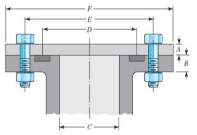
8-33 to 8-36 The figure illustrates the non-permanent connection of a steel cylinder head to a grade 30 cast- iron pressure vessel using N bolts. A confined gasket seal has an effective sealing diameter D. The cylinder stores gas at a maximum pressure pg. For the specifications given in the table for the specific problem assigned, select a suitable bolt length from the preferred sizes in Table A-17, then determine the yielding factor of safety np, the load factor nL, and the joint separation factor n0.
| Problem Number | 8-33 | 8-34 | 8-35 | 8-36 |
| A | 20 mm |
|
20 mm |
|
| B | 20 mm |
|
25 mm |
|
| C | 100 mm | 3.5 in | 0.8 m | 3.25 in |
| D | 150 mm | 4.25 in | 0.9 m | 3.5 in |
| E | 200 mm | 6 in | 1.0 m | 5.5 in |
| F | 300 mm | 8 in | 1.1 m | 7 in |
| N | 10 | 10 | 36 | 8 |
| pg | 6 MPa | 1500 psi | 550 kPa | 1200 psi |
| Bolt grade | ISO 9.8 | SAE 5 | ISO 10.9 | SAE 8 |
| Bolt spec. | M12 × 1.75 |
|
M10 × 1.5 |
|
The yield factor of safety.
The load factor of safety.
The joint separation factor.
Answer to Problem 36P
The yield factor of safety is
The load factor of safety is
The joint separation factor is
Explanation of Solution
Write the expression of the length of the material squeeze between the bolt face and washer face.
Here the length of the material squeeze between the bolt face and washer face is
Write the expression for the length of the bolt.
Here the length of bolt is
Write the expression of the threaded length for hexagonal bolt.
Here the threaded length is
Write the expression of the length of the unthreaded portion in grip.
Here, the length of the unthreaded portion in the grip is
Write the expression of the length of the threaded portion in grip.
Here, the length of threaded portion in the grip is
Write the expression of the major area diameter.
Here the nominal diameter of the bolt is
Write the expression of the stiffness for the bolt.
Here the bolt stiffness is
Write the expression of stiffness for the steel cylinder.
Here the stiffness of the steel cylinder is
Write the expression for the midpoint of the complete joint.
Here, the midpoint of the joint is
Write the expression of the thickness of the upper frustum.
Here, the thickness of upper frustum of the gasket is
Write the expression for the effective sealing diameter of the gasket sealing in upper frustum.
Here, the effective sealing diameter of upper frustum of the gasket sealing is
Write the expression for the stiffness of the upper frustum of cast iron vessel.
Here, the stiffness of the cast-iron pressure vessel in the upper frustum is
Write the expression for the stiffness of the lower frustum of the cast iron vessel.
Here, the stiffness of the cast-iron pressure vessel in the lower frustum is
Write the expression for the stiffness of the member or assembly.
Here, the stiffness of the member is
Write the expression of joint constant.
Here the joint constant is
Write the expression of initial tension in the bolt.
Here the tensile stress area is
Write the expression of the effective area of the cylinder.
Here, the effective area of the cylinder is
Write the expression for the total force acting on the assembly.
Here, the total load acting on the assembly is
Write the expression for the load acting on each bolt.
Here, the number of bolt is
Write the expression for yield factor of safety.
Here the overload factor of safety is
Write the expression of overload factor of safety.
Here the overload factor of safety is
Write the expression of joint separation factor of safety.
Here the factor of safety based on joint separation is
Conclusion:
Substitute
Refer to Table
Substitute
Substitute
Substitute
Substitute
Substitute
Refer to Table
Refer to Table
Substitute
Substitute
Substitute
Substitute
Substitute
Refer to Table
Substitute
Substitute
Substitute
Substitute
Refer to Table
Substitute
Substitute
Substitute
Substitute
Substitute
Thus, the yield factor of safety is
Substitute
Thus, the load factor of safety is
Substitute
Thus, the joint separation factor is
Want to see more full solutions like this?
Chapter 8 Solutions
Shigley's Mechanical Engineering Design (McGraw-Hill Series in Mechanical Engineering)


- Two plates are clamped by a 3/4-10 UNC SAE Grade 5 bolt and regular nut with a 3/4-W plain washer as shown in figure. Top plate is made of grey cast iron and bottom plate is steel. An axial force of 12kN is acted upon the joint. Round off the length of the bolt to nearest 1/4in. Assume bolts are preloaded to 75% of proof load. 1. Determine the bolt stiffness kb. 2. Determine the member stiffness km. 3. Determine the yielding factor of safety of the bolt. 4. Determine the load factor for the bolt. 5. Determine the load factor guarding against joint separation. 1.25 in 1.00 inarrow_forwardRequired information The bolted connection shown in the figure is subjected to a tensile shear load of 90 kN. The bolts are ISO class 5.8, and the material is cold-drawn AISI 1015 steel. Assume the bolt threads do not extend into the joint. Find the factor of safety of the connection for all possible modes of failure. Give the overall joint factor of safety. Given: t = 15 mm and t2 = 25 mm. NOTE: This is a multi-part question. Once an answer is submitted, you will be unable to return to this part. 35 60 60 - 35 t1 M20 x 2.5 35 35 + t2 Find the overall joint factor of safety. The overall joint factor of safety noverall isarrow_forwardExample 8-4 in SI Units. • Q-2 Figure gives the cross section of a grade 25 cast-iron pressure vessel. A total of N bolts are to be used to resist a M16 x 2 x 60 mm class 5.8 separating force of 36 kip (160.2 kN). • (a) Determine k,, Kmy and C. • (b) Find the number of bolts required for a load factor of 2 where the bolts may be reused when the joint is taken apart. hexagonal head bolt No: 25 CI 20 mm 20 mm • (c) With the number of bolts obtained in part (b), determine the realized load factor for overload, the yielding factor of safety, and the load factor for joint separation. H = 14.8 mmarrow_forward
- The figure gives the cross-section of a grade 25 cast-iron pressure vessel. A total of N bolts are to be used to resist a separating force of 150 kN. (a) Determine kb, km, and C. (b) Find the number of bolts required for a load factor of 2 where the bolts may be reused when the joint is taken apart. (c) With the number of bolts obtained in part (b), determine the realized load factor for overload, the yielding factor of safety, and the load factor for joint separation. Use (SI) units as it appliesarrow_forwardThe figure shows a connection that employs three SAE grade 4 bolts. The tensile shear load on the joint is 4000 lbf. The members are bars of AISI 1020 HR steel. Assume the bolt threads do not extend into the joint. Find the factor of safety for each possible mode of failure. (Refer example problem 8.6 on pg. 445). in ∞ in 100 in 1 in in Đ 1in -2 in in-20 UNC 5 5 in inarrow_forwardProblem 3: A Hexagonal bolt connects two members. The joint has a gap 1 = 2 in and the applied load is 2000 lb. Both of the clamped parts are steel. A preload of 90% the bolt's proof strength will be applied first. For this design, an SAE grade 1, 5/16"-18 UNC-2A bolt is chosen made from A307 with rolled threads. Washers are included between the head and the joint, and between the nut and the joint. Determine a suitable length for the bolt? Find its safety factor against yielding and against joint separation. Are these values acceptable?arrow_forward
- D Problem Number A B C D E F N (d) Calculate the connection / joint stiffness. (e) Calculate the bolt stiffness. Ps Bolt grade Bolt spec. (a) Determine the force on the end plate. (b) Calculate the nominal force per bolt w/o preload. (c) Calculate the nominal stress in the bolt w/o preload. 8-34 An end plate is loaded by the gas pressure inside a pipe. N is the total number of bolts. Assume the pipe / plate material is ASTM A36 steel. The bolts are 2.0 inches long with a threaded length of 1.25 inches. The nut thickness is 0.50 inches. For the data specified in column 8-34: in 3.5 in 4.25 in 6 in 8 in 10 1500 psi SAE 5 in-13 (f) Assuming safety factor of Q = 1.25 for the connection, calculate the required bolt preload. (g) Calculate the maximum force in the bolt. (h) Calculate the maximum stress in the bolt. (i) Calculate the torque required to establish the bolt preload.arrow_forwardA link in a mechanism is to be subjected to a tensile force that varies from 3500 to 500 N in acyclical fashion as the mechanism runs. It has been decided to use AISI 1040 cold-drawn steel.Complete the design of the link, specifying a suitable cross-sectional shape and dimensions.5. Specify the required length of no. 60 chain to mount on sprockets having 15 and 50 teeth with acenter distance of no more than 36 in.arrow_forward1. For a bolted assembly with six bolts, the stiffness of each bolt is k, = 3 Mlbf/in and the stiffness of the members is km = 12 Mlbf/in per bolt. An external load of 80 kips is applied to the entire joint. Assume the load is equally distributed to all the bolts. It has been determined to use 1/2 in-13 UNC grade 8 bolts with rolled threads. Assume a torque co-efficient of K = 0.2. a. Determine the maximum bolt preload that can be applied without exceeding the proof strength of the bolts. b. Determine the minimum bolt preload that can be applied while avoiding joint separation. c. Determine the value of torque in units of Ibf-ft that should be specified for preloading the bolts if it is desired to preload to 75% of the proof load. d. Determine the yielding factor of safety for part c). (based on proof strength)arrow_forward
- Calculate the maximum tensile stress developed in a 1/4-20 bolt (Major dia = 0.2500" and Root dia = 0.1959"), 3" long, and a head height of 0.1875", if it is subjected to a load of 426 lbs.arrow_forwardThe cantilever bracket is bolted to a column with three M12x1.75 ISO 5.8 bolts. The bracket is made from AISI 1020 hot-rolled steel. Find the factors of safety for the following failure modes: shear of bolts, bearing of bolts, bearing of bracket, and bending of bracket. Lazima 36 36 Holes for M12x 1.75 bolts 8 mm thick 200- 12 ANarrow_forwardCalculate the dimensions of the I-section of a connecting rod, stating any assumptions. using the data below: Maximum cylinder pressure = 3.15N/mm² Cylinder bore = 100mm Factor of Safety=6 Crank length 95mm Connecting rod length=380mm Take the constant a=7500.arrow_forward
 Elements Of ElectromagneticsMechanical EngineeringISBN:9780190698614Author:Sadiku, Matthew N. O.Publisher:Oxford University Press
 Mechanics of Materials (10th Edition)Mechanical EngineeringISBN:9780134319650Author:Russell C. HibbelerPublisher:PEARSON
 Thermodynamics: An Engineering ApproachMechanical EngineeringISBN:9781259822674Author:Yunus A. Cengel Dr., Michael A. BolesPublisher:McGraw-Hill Education
 Control Systems EngineeringMechanical EngineeringISBN:9781118170519Author:Norman S. NisePublisher:WILEY
 Mechanics of Materials (MindTap Course List)Mechanical EngineeringISBN:9781337093347Author:Barry J. Goodno, James M. GerePublisher:Cengage Learning
 Engineering Mechanics: StaticsMechanical EngineeringISBN:9781118807330Author:James L. Meriam, L. G. Kraige, J. N. BoltonPublisher:WILEY