
Concept explainers
Videos
A solenoid is an arrangement of many current loops placed together as shown below. The current through each loop is the same and is in the direction shown.
Obtain or draw an enlargement of the figure.
1. At each of the labeled points, draw a vector to indicate the direction and magnitude of the magnetic field. Use the principle of superposition in determine your answer.
2. Sketch magnetic field lines on the enlargement.
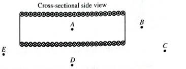
Describe the magnetic field near the center of the solenoid.
3. How does the field of the solenoid a points A-E compare with that of a bar magnet (both inside and outside?
Which end of the solenoid corresponds to a north pole? Which end corresponds to a south pole?
4. How would the magnetic field at any point within the solenoid be affected by the following changes? Explain your reasoning in each case.
• The current through each coil of the solenoid is increased by a factor of two.
• The number of coils in each unit length of the solenoid is increased by a factor of two, with the current through each coil remaining the same.

Trending nowThis is a popular solution!

Learn your wayIncludes step-by-step video

Chapter 7 Solutions
Tutorials in Introductory Physics
Additional Science Textbook Solutions
Conceptual Physics (12th Edition)
University Physics Volume 1
The Cosmic Perspective
Physics (5th Edition)
Cosmic Perspective Fundamentals
College Physics (10th Edition)


- 4. Use the picture as a reference for answering A and B. 4A. Determine the magnetic field at point A, assuming that the current is increasing and charging the metal plates (with surface charge density and radius R). 4B. Determine the magnetic field at point B, assuming that the current is increasing, and charging the metal plates (with surface charge density and radius R). NOTE: The answers for A and B should be in formula form.arrow_forwardDirection: Answer the following problems below. 1. A proton moving at a speed of 75,000 m/s horizontally to the right enters a uniform magnetic field of 0.050 T which is directed vertically downward. Find the direction and magnitude of the magnetic force on the proton. 2. A 0.5 m long wire carries a current of 2.0 A in a direction perpendicular to a 0.3 T magnetic field. What is the magnitude of the magnetic force acting on the wire?arrow_forwardTwo wires lie perpendicular to the plane of the paper and equal electric currents pass through the paper in the directions shown. Point P is equidstant from the two wires. a) Construct a vector diagram showing the direction of the resultant magnetic field at point P due to currents in these wires. Explain your reasoning. b) If the currents in both wires were instead directed into the plane of the page (such that the current moved away from us), show the resultant magentic field at point P.arrow_forward
- Look at the scenario on the bottom left. Here a bar magnet has been broken into two pieces. Make a drawing of the part of the magnetic circled in red. (1) Clearly identify the pole where the red question mark is by adding an N or S in your drawing. Then (2) draw the magnetic field lines for the bar magnet in the google drawing. Make sure to show the direction of your field lines by including arrow heads. 5arrow_forwardThe right half of the square loop of wire shown in (Figure 1) is in a 0.85 T magnetic field directed into the page. The current in the loop is 1.1 A in a clockwise direction. 1. What is the magnitude of the force on the loop? Express your answer with the appropriate units. 2. In which direction does this force act? A. to the left B. upward C. downward D. to the rightarrow_forwardA. Use Biot-Savart’s law to find the magnitude of the magnetic field at the center of a quarter-circle of wire of radius ?, carrying current ?. Show all your work. B. Give, also, the direction of the magnetic field at the center of a quarter-circle.arrow_forward
- A 10 cm wire carrying a current of 20 A is placed in a uniform magnetic field of 0.3 T. ifthe wire makes an angle of 40° with the vector of magnetic field, find the magnitude ofthe force on the wire.2. Should you expect that a straight line would go through the origin for each experiment?3. What assumptions are made in each experiment about the magnetic field produced by themagnets?4. Summarize the results of the 3 experiments and discuss how they are related to Equationarrow_forwardConsider the setup as shown in Figure 5. Given the direction of the magnet field and current flow, determine the balance reading (Hint: use the right-hand rule and Newton's Third Law). Draw a free-body diagram of the Magnet Assembly in equilibrium with the current flowing through the circuit. Predict whether the electronic balance will read a positive value or a negative value. B field going into the paper X X X X X X X X X X X X X X X X X X X X X X X X X X X X X X X X X X X X Balance Side view Figure 5 Īarrow_forwardFigure 3 shows a straight wire carrying a current in upwarddirection. The wire is placed near a wire loop. For each case described below, answer the following questions:a. What is the direction of the magnetic flux through theloop?b. Is the magnitude of the flux through the loop increasing ordecreasing with time?c. What is the direction of the magnetic field produced by theinduced current in the loop?d. What is the direction of the current induced in the loop?1. Case 1: The current is increasing.2. Case 2: The current is decreasing.3. Case 3: The current is constant but the loop is being pulledaway from the straight wire.arrow_forward
- Please refer to Figure 2 included in this folder. For the moment please disregard the moving charge off to the right. The diagram above shows segments of two long straight wires, carrying currents I_1 = 5.95 A and I_2 = 1.08 A respectively. The distance between the wires is 1.40 cm. What is the force on a 5.52-cm segment of wire #2 due to the magnetic field from wire #1? 9.63E-06 N 5.07E-06 N 2.54E-06 N 7.61E-06 Narrow_forwardIn the figure below, a coil of wire is wound around a segment with magnetic flux directed as shown. The coil of wire is connected to a resistive load (not shown in the figure). If the magnetic flux is constant, what will be the direction of the current i2 on the upper section of the wire (that is, which of the red arrows will be correct, if any)? O a. Insufficient information is given. O b. To the left O c. To the right O d. No current will be induced. corearrow_forwardSolve the following problems. Show all necessary solutions to justify your answers. All final answer must be up to the 3rd decimal places with the appropriate units. What is the direction of the magnetic force on a positive charge that moves as shown?arrow_forward
 College PhysicsPhysicsISBN:9781305952300Author:Raymond A. Serway, Chris VuillePublisher:Cengage Learning
 University Physics (14th Edition)PhysicsISBN:9780133969290Author:Hugh D. Young, Roger A. FreedmanPublisher:PEARSON
 Introduction To Quantum MechanicsPhysicsISBN:9781107189638Author:Griffiths, David J., Schroeter, Darrell F.Publisher:Cambridge University Press
 Physics for Scientists and EngineersPhysicsISBN:9781337553278Author:Raymond A. Serway, John W. JewettPublisher:Cengage Learning
 Lecture- Tutorials for Introductory AstronomyPhysicsISBN:9780321820464Author:Edward E. Prather, Tim P. Slater, Jeff P. Adams, Gina BrissendenPublisher:Addison-Wesley
 College Physics: A Strategic Approach (4th Editio...PhysicsISBN:9780134609034Author:Randall D. Knight (Professor Emeritus), Brian Jones, Stuart FieldPublisher:PEARSON