
International Edition---engineering Mechanics: Statics, 4th Edition
4th Edition
ISBN: 9781305501607
Author: Andrew Pytel And Jaan Kiusalaas
Publisher: CENGAGE L
expand_more
expand_more
format_list_bulleted
Concept explainers
Videos
Textbook Question
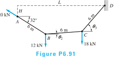
Chapter 6, Problem 6.91P
For the cable ABCD determine (a) the angles
Expert Solution & Answer
Want to see the full answer?
Check out a sample textbook solution
Students have asked these similar questions
2. Given the cantilever framework below, find the shortest distance from point B to
line AC and to line AD.
8'
A
3. In the system shown below, determine the length of the common perpendicular
between lines AE and BD. Solve in two ways.
W = 2200 Ib
4. If the magnitude of a force P acting from A to D is P = 20V73 Ib, determine the
component of P that is perpendicular to the plane defined by points E, A, and C.
10'
B
with the following modifications:
Replace the vertical 6kN at point B with a horizontal force 6kN acting to the right at the same point.
2. Four forces are applied to the machine element
ABDE as shown to the left. Find the resultant
200 mm
force and the resultant moment at point A.
(Assume that points A, B, D, and E are located at
the centroid of the cross-section of the bar, and
that the forces act at these points.)
50 N
40 mm
20 mm
B.
300 N
R =-420î – 50ĵ– 250k N
Ans.:
160 mm
M, =0î +30.8ĵ –22k N - m
250 N
D
A
100 mm
E
120 N
Chapter 6 Solutions
International Edition---engineering Mechanics: Statics, 4th Edition
Ch. 6 - Determine the internal force system acting on...Ch. 6 - Determine the internal force system acting on...Ch. 6 - Determine the internal force system acting on...Ch. 6 - Find the internal force systems acting on sections...Ch. 6 - Find the internal force systems acting on sections...Ch. 6 - Find the internal force systems acting on sections...Ch. 6 - The three identical cantilever beams carry...Ch. 6 - Determine the internal force systems acting on...Ch. 6 - For the structural component shown, determine the...Ch. 6 - Compute the internal force system acting on...
Ch. 6 - Determine the internal force system acting on...Ch. 6 - Determine the internal force systems acting on...Ch. 6 - Determine the internal force systems acting on...Ch. 6 - Find the internal force system acting on section 3...Ch. 6 - The structure is supported by a pin at C and a...Ch. 6 - The 1800lbin. couple is applied to member DEF of...Ch. 6 - A man of weight W climbs a ladder that has been...Ch. 6 - For the ladder in Prob. 6.17, find the internal...Ch. 6 - Determine the internal force system acting on...Ch. 6 - The equation of the parabolic arch is y=(36x2)/6,...Ch. 6 - For the beam shown, derive the expressions for V...Ch. 6 - For the beam shown, derive the expressions for V...Ch. 6 - For the beam shown, derive the expressions for V...Ch. 6 - For the beam shown, derive the expressions for V...Ch. 6 - For the beam shown, derive the expressions for V...Ch. 6 - For the beam shown, derive the expressions for V...Ch. 6 - For the beam shown, derive the expressions for V...Ch. 6 - For the beam shown, derive the expressions for V...Ch. 6 - For the beam shown, derive the expressions for V...Ch. 6 - For the beam shown, derive the expressions for V...Ch. 6 - For the beam shown, derive the expressions for V...Ch. 6 - For the beam shown, derive the expressions for V...Ch. 6 - For the beam shown, derive the expressions for V...Ch. 6 - For the beam shown, derive the expressions for V...Ch. 6 - For the beam shown, derive the expressions for V...Ch. 6 - For the beam shown, derive the expressions for V...Ch. 6 - For the beam shown, derive the expressions for V...Ch. 6 - For the beam shown, derive the expressions for V...Ch. 6 - Derive the shear force and the bending moment as...Ch. 6 - Derive the shear force and the bending moment as...Ch. 6 - The 24-ft timber floor joist is designed to carry...Ch. 6 - For the beam AB shown in Cases 1 and 2, derive and...Ch. 6 - Construct the shear force and bending moment...Ch. 6 - Construct the shear force and bending moment...Ch. 6 - Construct the shear force and bending moment...Ch. 6 - Construct the shear force and bending moment...Ch. 6 - Construct the shear force and bending moment...Ch. 6 - Construct the shear force and bending moment...Ch. 6 - Construct the shear force and bending moment...Ch. 6 - Construct the shear force and bending moment...Ch. 6 - Construct the shear force and bending moment...Ch. 6 - Construct the shear force and bending moment...Ch. 6 - Construct the shear force and bending moment...Ch. 6 - Construct the shear force and bending moment...Ch. 6 - Construct the shear force and bending moment...Ch. 6 - Construct the shear force and bending moment...Ch. 6 - Draw the load and the bending moment diagrams that...Ch. 6 - Draw the load and the bending moment diagrams that...Ch. 6 - Draw the load and the bending moment diagrams that...Ch. 6 - Draw the load and the bending moment diagrams that...Ch. 6 - Draw the load and the bending moment diagrams that...Ch. 6 - Show that the tension acting at a point in a...Ch. 6 - The cable of the suspension bridge spans L=140m...Ch. 6 - The two main cables of the Akashi Kaikyo...Ch. 6 - Cable AB supports the uniformly distributed load...Ch. 6 - A uniform 80-ft pipe that weighs 960 lb is...Ch. 6 - The cable AB supports a uniformly distributed load...Ch. 6 - The string attached to the kite weighs 0.4 oz/ft....Ch. 6 - Show that the tension acting at a point in a...Ch. 6 - A uniform cable weighing 16 N/m is suspended from...Ch. 6 - The tensions in the cable at points O and B are...Ch. 6 - The cable AOB weighs 24 N/m. Determine the sag H...Ch. 6 - The cable of mass 1.8 kg/m is attached to a rigid...Ch. 6 - One end of cable AB is fixed, whereas the other...Ch. 6 - The end of a water hose weighing 0.5 lb/ft is...Ch. 6 - The 50-ft measuring tape weighs 2.4 lb. Compute...Ch. 6 - The cable AOB weighs 5.2 N/m. When the horizontal...Ch. 6 - The chain OA is 25 ft long and weighs 5 lb/ft....Ch. 6 - The 110-lb traffic light is suspended from two...Ch. 6 - The cable carrying 60-lb loads at B and C is held...Ch. 6 - The cable ABCD is held in the position shown by...Ch. 6 - Find the forces in the three cable segments and...Ch. 6 - The cable carrying three 400-lb loads has a sag at...Ch. 6 - The cable supports three 400-lb loads as shown. If...Ch. 6 - Cable ABC of length 5 m supports the force W at B....Ch. 6 - When the 12-kN load and the unknown force P are...Ch. 6 - The cable is loaded by an 80-lb vertical force at...Ch. 6 - The 15-m-long cable supports the loads W1 and W2...Ch. 6 - The cable of length 15 m supports the forces...Ch. 6 - The 14-kN weight is suspended from a small pulley...Ch. 6 - For the cable ABCD determine (a) the angles 2 and...
Knowledge Booster


Learn more about
Need a deep-dive on the concept behind this application? Look no further. Learn more about this topic, mechanical-engineering and related others by exploring similar questions and additional content below.Similar questions
- 3.30 For the truss and loading shown, determine the resultant of the loads and the distance from point A to its line of action. R d 4 kips 3 kips 2 kips D E 6 ft В 8 ft 8 ft 8 ft 8 ftarrow_forwardQ1: Determine the moments about point ( A ) due to the forces applied on the cantilevered beam. 4 kN 30° 30° 2 m 6 kN 2 m -- 2 marrow_forwardFive forces and a couple act on the plate shown in the figure . - Find the resultant ( R ) Of the four forces , and its angle (e). - Locate it with respect to point ( O). - Show where the resultant cuts both the x - and y- axes. 400KN 7m 1o0 KN 6 m lom 800 KN-m V150 KN 18m 7200KN 100 KN L 8 marrow_forward
- Q.2) For the system of forces shown in figure, replace the forces in the wires with an equivalent force R that passes through point A, and determine the y-coordinate of point A. 240 N 300 N 25 12m 1.2 marrow_forwardDetermine the moment produced about the CD-axis if the tension in rope AB is 300 lb. (a) Write the tension force in rope AB in vector form. (b) Write the unit vector in the direction of CD-axis. (c) Write the position vector between CD and AB required to calculate moment about an axis. (d) Determine the moment produced by tension in AB about the CD-axis. 9 in 16 in 16 in 8 in y 8'in C 18 inarrow_forwardFind the internal force systems acting on sections 1 and 2.arrow_forward
- A 30 N force acts on the end of the 3 m lever as shown. The moment of the force about '0' is : 20° 30 N 3 m 50 A:- 30.8 N-m - (Correct Alternative) B: 30.8 N-m C:- 12.72 N-m D: 12.72 N-marrow_forward80 mm 240 mm 80 mm 240 mm D 300 mm A rectangular plate is supported by brackets at A and B and by a wire CD. If the tension in the wire is 200 N, determine the moment along an axis from A to B of the force exerted by the wire on point C.arrow_forwardFind the moment about A, C, and F for the forces acting on the link shown below. Point C is at the center of B and D. Take F1 = 49 N, F2 = 16 N, F3 = 21 N, F4 = 28 N, F5 = 41 N and F6 = 24 N. F1 F5 4m 7 F6 6m 4m A B F2 F3 Solution: (i) Moment about A in Nm is (ii) Moment about C in Nm is (iii) Moment about F in Nm is C I 10m E F4 60°arrow_forward
- Find the moment about A, B, & C, where AB = AD = 19 m, F₁= 3 N, F₂ = 7 N, F3 = 11 N & F4 = 19 N. Each force is acting at the mid-point of each side. --(3 Marks) F4 F₁ F3 B F2 (NOTE: ENTER ONLY THE VALUES BY REFERRING TO THE UNITS GIVEN IN THE BRACKET) The moment of force about "A" (in Nm) = The moment of force about "B" (in Nm) = The moment of force about "C" (in Nm) =arrow_forwardExample : Replace the three forces acting on the bent beam by a single equivalent force R. Specify the distance x from the point O in which the line of action of R passes. 200 N 一 160 N 250 mm 250 mm -250 mm 240 N - 125 mmarrow_forwardCompute the combined moment of the two 75-lb forces about (a) point O and (b) point A. The moment is positive if counterclockwise, negative if clockwise. Assume a = 7.2 in., b = 3.4 in., F = 75 lb. Answers: (a) Mo= (b) MA= i y lb-in. lb-in.arrow_forward
arrow_back_ios
SEE MORE QUESTIONS
arrow_forward_ios
Recommended textbooks for you
 International Edition---engineering Mechanics: St...Mechanical EngineeringISBN:9781305501607Author:Andrew Pytel And Jaan KiusalaasPublisher:CENGAGE L
International Edition---engineering Mechanics: St...
Mechanical Engineering
ISBN:9781305501607
Author:Andrew Pytel And Jaan Kiusalaas
Publisher:CENGAGE L
Engineering Basics - Statics & Forces in Equilibrium; Author: Solid Solutions - Professional Design Solutions;https://www.youtube.com/watch?v=dQBvQ2hJZFg;License: Standard YouTube License, CC-BY