
Videos
Find the current
Answer to Problem 56E
The current
Explanation of Solution
Given data:
Value of voltage
Value of resistances
Calculation:
The redrawn circuit is shown in Figure 1 as follows.
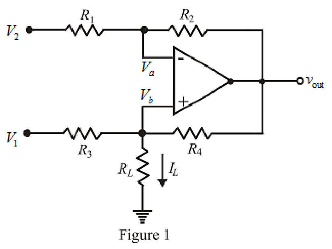
Refer to the Figure 1.
The expression for nodal analysis at node voltage
Here,
The expression for nodal analysis at node voltage
Here,
The expression for the virtual ground concept is as follows,
The expression for current
Here,
Simplify equation (1) for
Simplify the equation (2).
Substitute
Rearrange for
Simplify for
Substitute
Substitute the value of
Substitute
Conclusion:
Thus, the current
Want to see more full solutions like this?
Chapter 6 Solutions
Loose Leaf for Engineering Circuit Analysis Format: Loose-leaf


- A battery is comprised of 4 cells connected in parallel, each cell has an EMF with 1.5V and an internal resistance of 600.00 mΩ. There is no load connected to the terminal. Solve for Rint.arrow_forward6.51 Detemine Leq at terminals a-b of the circuit in Fig. 6.73. 10 mH all 60 mH 25 mH 20 mH a o 30 mH llarrow_forward3. Given the measured value of Vp in Fig. 6.69, determine: (а) Ip. (b) VDs- (c) VGG- 14 V 1.6 k2 Vp=9 V Ipss-8 mA Vos V =-4V 1 MA Figure 6.69arrow_forward
- the capacitor assuming that the valse of 4.Find the voltage across vi(() = 10e'u(1) for the circuit in figure below. Here assume that at t=0, voltage across the capacitor is vot) =5v, 102 + 10cu(1) ) O 102 v(1)+0.1F 28(1)Aarrow_forward6.20 Find the equivalent capacitance at terminals a-b of the circuit in Fig. 6.54. a 1 µF- 1 µF 2 µF + 2 µF 2 µF 3 µF 3 µF 3 µF 3 µFarrow_forwardPractice Problem 6. Find the voltage across each of the capacitors in Fig. 6.20. 40 μF 60 µF Answer: U= 45 V, U2 = 45 V, v3 = 15 V, v4 30 V. + 1 - + v3 - 90 V 20 μF 30 V4 Figure 6.20 For Practice Prob. 6.7.arrow_forward
- 6.23 Using Fig. 6.57, design a problem that will help end other students better understand how capacitors work together when connected in series and in parallel. C1 C3 V C2 C4arrow_forwardL1 L2 AO- 3 mH 5 mH L4 9 mH L3 6 mH L8 L5 12 mH 10 mH Determine teh total inductance of teh circuit shown in Fig. 6. L7 L6 Во- 4 mH 7 mH L9 15 mH Figure 6arrow_forwardThe measuring range of a MC instrument is found to be (0 – 800) mA. This low range instrument is connected with a multiplier resistance of 120 Ω, in order to measure potential difference up to 120V. Determine the resistance of the instrumentarrow_forward
- under steady-state dc conditions find i and v in the circuit in Fig. 6.71arrow_forwardA certain solar cell type has an output capability of 9.2 A at 0.7 V. A series / parallel solar array has been designed of such cells with 11 parallel strings and each string has 114 cells in series. Calculate Voltage capability of array.arrow_forward6.19 Find the equivalent capacitance between terminals a and b in the circuit of Fig. 6.53. All capacitances are in uF. 80 12 40 a 50 20 12 30 10 bo 60arrow_forward
 Introductory Circuit Analysis (13th Edition)Electrical EngineeringISBN:9780133923605Author:Robert L. BoylestadPublisher:PEARSON
 Delmar's Standard Textbook Of ElectricityElectrical EngineeringISBN:9781337900348Author:Stephen L. HermanPublisher:Cengage Learning
 Programmable Logic ControllersElectrical EngineeringISBN:9780073373843Author:Frank D. PetruzellaPublisher:McGraw-Hill Education
 Fundamentals of Electric CircuitsElectrical EngineeringISBN:9780078028229Author:Charles K Alexander, Matthew SadikuPublisher:McGraw-Hill Education
 Electric Circuits. (11th Edition)Electrical EngineeringISBN:9780134746968Author:James W. Nilsson, Susan RiedelPublisher:PEARSON
 Engineering ElectromagneticsElectrical EngineeringISBN:9780078028151Author:Hayt, William H. (william Hart), Jr, BUCK, John A.Publisher:Mcgraw-hill Education,