
Concept explainers
Videos
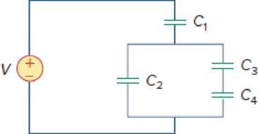
Using Fig. 6.57, design a problem that will help other students better understand how capacitors work together when connected in series and in parallel.
Figure 6.57
Design a problem to make better understand how capacitors work together when connected in series and in parallel using Figure 6.57.
Explanation of Solution
Problem design:
For the circuit in Figure 6.57, determine the voltage across each capacitor and the energy stored in each capacitor.
Formula used:
Write the expression to calculate the energy stored in the capacitor.
Here,
Calculation:
Refer to Figure 6.57 in the textbook. The Figure 6.57 is redrawn as Figure 1 by assuming the voltage and capacitor values.
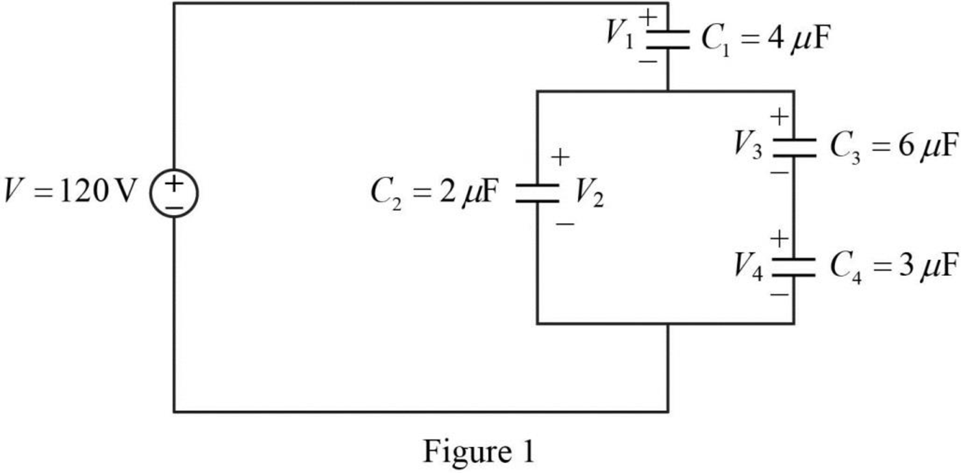
Refer to Figure 1, the capacitors
Write the expression to calculate the equivalent capacitance 1 for the series connected capacitors
Here,
Substitute
The reduced circuit of the Figure 1 is drawn as Figure 2.
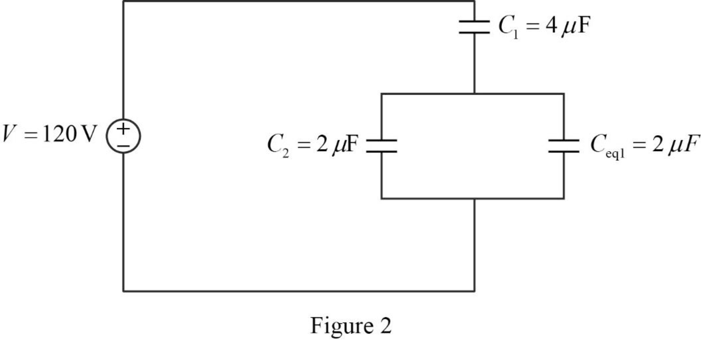
Refer to Figure 2, the capacitors
Write the expression to calculate the equivalent capacitance 2 for the parallel connected capacitors
Here,
Substitute
The reduced circuit of the Figure 2 is drawn as Figure 3.
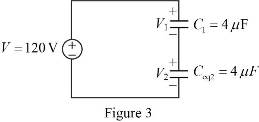
Write the expression to calculate the total applied voltage.
Here,
From the Figure 3, it is clear that the voltage across the capacitors with same capacitance value is equal. Therefore,
Substitute
Simplify the above equation to find
Therefore, from equation (5),
Write the expression to calculate the charge across the capacitor 1.
Here,
Substitute
Write the expression to calculate the charge across the capacitor 2.
Substitute
Refer to Figure 2, the capacitors
The combination of the series connected capacitors
Write the expression to calculate the voltage across the capacitor 3.
Substitute
Write the expression to calculate the voltage across the capacitor 4.
Substitute
Re-write the equation (1) to calculate the energy stored in capacitor
Substitute
Re-write the equation (1) to calculate the energy stored in capacitor
Substitute
Re-write the equation (1) to calculate the energy stored in capacitor
Substitute
Re-write the equation (1) to calculate the energy stored in capacitor
Substitute
Therefore, the value of the voltage across the capacitor 1
Conclusion:
Thus, the problem to make better understand how capacitors work together when connected in series and in parallel using Figure 6.57 is designed.
Want to see more full solutions like this?
Chapter 6 Solutions
Fundamentals of Electric Circuits


- Three capacitors having capacitance values of 20F,40F, and 50F are connected in parallel to a 60 - Hz power line. An ammeter indicates a circuit current of 8.6 amperes. How much current is flowing through the 40F capacitor?arrow_forwardYou are an electrician working in an industrial plant. You discover that the problem with a certain machine is a defective capacitor. The capacitor is connected to a 240-volt AC circuit. The information on the capacitor reveals that it has a capacitance value of 10 mF and a voltage rating of 240 VAC. The only 10-mF AC capacitor in the storeroom is marked with a voltage rating of 350 WVDC. Can this capacitor be used to replace the defective capacitor? Explain your answer.arrow_forwardB. A parallel-plate capacitor is constructed from two metal dics of radius 1 cm with a gap 0.05 cm thick filled with mica. a) What is the capacitance? b) What is the charge of this capacitor after being connected to a 100- V battery?arrow_forward
- Please draw the problem and answer, thanks for the help. A capacitor is made of 2 rectangular metal plates with side length of 3 cm x 6 cm separated by a distance of 2.36 cm with water in between the plates. The capacitor has a voltage of 110 v and is not connected to a battery. Calculate the capacitance. What is the new capacitance if we replace water with a new dielectric material with a constant of 3.75 in between the plates? What is the new voltage? What is the charge on each plate?arrow_forwardThree capacitors are connected in parallel across a 230 V, 60 Hz supply. These capacitors have values of 10 µF, 30 µF, and 60 µF, respectively. A single capacitor can replace the three capacitors. What value of capacitance is required to do this? Determine the total current taken by the three capacitors. What is the current in the 10 µF capacitorarrow_forwardThe illustration shows four capacitors that are connected together in a so-called capacitor bridge. Initially, the capacitors are uncharged. Which relationship must hold between the four capacitances so that the voltage between points c and d remains zero when a voltage U is applied between points a and b?arrow_forward
- 6. The total capacitance of two 40-mF series-connected capacitors in parallel with a 70-mF capacitor is?arrow_forwardA 15 V, 10 µF capacitor is connected in series with an uncharged 5 µF capacitor. The combination is connected across a 50 V battery. Find the new potential differences across each capacitors after the switch is closed.arrow_forwardThe arrangement of several capacitors is shown in the figure below with each capacitance value, namely C1 = C5 = C6 = 6 µF and C2 = C3 =C4=4 µF. Then the capacitor arrangement is connected to a battery with a value of V = 12 V. Determine the total charge stored in all the capacitors and what is the charge on the capacitor C5arrow_forward
- Which of the following is TRUE? O a) The major reason for using electrolytic capacitors is that they have a very low a) capacitance but can handle very low voltages. O b) Increasing the distance between the plates of a capacitor would yield a higher capacitance. OdA capacitor is rated according to its maximum allowable voltage and c) capacitance value. d) Electrolytic capacitors are non-polarized.arrow_forwardA fully charged capacitor has a voltage of 100V and is then discharged through a resistor. The potential difference across the capacitor is 1V after 10 seconds. What is the time constant of the circuit?arrow_forwardA 2000 µF capacitor is charged by a constant current dc source. After 100 seconds, the voltage across the capacitor raises from 100 Vdc to 200 Vde. Calculate the charging current and charge on the capacitor in coulombs.arrow_forward
 Delmar's Standard Textbook Of ElectricityElectrical EngineeringISBN:9781337900348Author:Stephen L. HermanPublisher:Cengage Learning