
Concept explainers
Videos
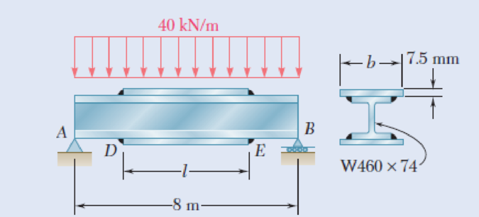
Two cover plates, each 7.5 mm thick, are welded to a W460 × 74 beam as shown. Knowing that σall = 150 MPa for both the beam and the plates, determine the required value of (a) the length of the plates, (b) the width of the plates.
Fig. P5.144 and P5.145
(a)
Find the length of the plates.
Answer to Problem 145P
The length of the plates is
Explanation of Solution
The length of the cover plate is
The thickness of the cover plate is
The width of the cover plate is
The allowable normal stress in the beam is
Show the free-body diagram of the prismatic beam as in Figure 1.
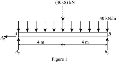
Determine the vertical reaction at point B by taking moment at point A.
Determine the vertical reaction at point A by resolving the vertical component of forces.
Show the free-body diagram of the section AD as in Figure 2.
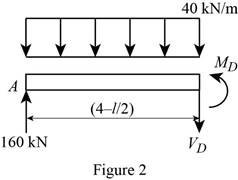
Determine the moment at point D by taking moment about point D.
Refer to Appendix C “Properties of Rolled-Steel Sections” in the textbook.
The section modulus of the
Determine the moment at point D
Here, the allowable stress of the beam is
Substitute 150 MPa for
Find the length of the plate using trial and error method.
Therefore, the length of the plates is
(b)
Find the width of the plates.
Answer to Problem 145P
The width of the plates is
Explanation of Solution
The length of the cover plate is
The thickness of the cover plate is
The width of the cover plate is
The allowable normal stress in the beam is
Show the free-body diagram of the prismatic beam as in Figure 3.

Determine the vertical reaction at point B by taking moment at point A.
Determine the vertical reaction at point A by resolving the vertical component of forces.
Show the free-body diagram of the section AC as in Figure 4.
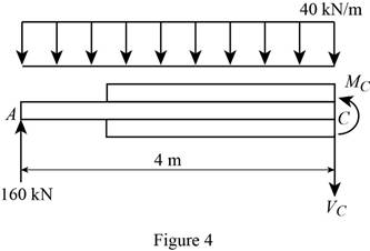
Determine the moment at point C by taking moment about point C.
Show the cross section of the beam as in Figure 5.
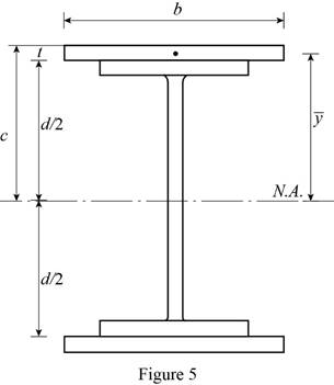
Determine the section modulus (S) of the beam using the relation.
Here, the allowable normal stress in the beam is
Substitute
Refer to Appendix C “Properties of Rolled-Steel Sections” in the textbook.
The depth of the
The moment of inertia of the
Determine the moment of inertia (I) of the beam using the relation;
Here, the moment of inertia of the beam is
Refer to the cross section of the beam;
Substitute
Determine the distance from the neutral axis (c) to outer most fibre as follows;
Determine the width of the plates (b) using the relation.
Substitute
Therefore, the width of the plates is
Want to see more full solutions like this?
Chapter 5 Solutions
Mechanics of Materials, 7th Edition


- Homework A timber beam AB of length L and rectangular cross section carries a single concentrated load P at its midpoint C. (a) Show that the ratio Tm/0, of the maximum values of the shearing and normal stresses in the beam is equal to h/2L, where h and L are, respectively, the depth and the length of the beam. (b) Determine the depth h and the width b of the beam, knowing that L = 2 m, P = 40 kN, 7,m = 960 kPa, and om 12 MPa. %3D L/2- - L/2 16|- Вarrow_forwardA steel bar and an aluminum bar are bonded together to form the composite beam shown. The modulus of elasticity for aluminum is 70 GPa and for steel is 200 GPa. Knowing that the beam is bent about a horizontal axis by a couple of moment M= 1500 N·m, determine the maximum stress in (a) the aluminum, (b) the steel.arrow_forwardTwo wooden boards, measuring 15 mm thick and 225 mm wide, are joined by the socket joint shown. Knowing that the wood employed will break when the average shear stress reaches 10 MPa, determine the intensity P of the axial force that will break the joint.arrow_forward
- A 1600-lb-in. couple is applied to a wooden beam, of rectangular cross section 1.5 by 3.5 in., in a plane forming an angle of 308 with the vertical (Fig. ). Determine (a) the maximum stress in the beam and (b) the angle that the neutral surface forms with the horizontal planearrow_forwardL/4 D L/2 LA B A timber beam AB of length L and rectangular cross section carries a uniformly distributed load w and is supported as shown. (a) Show that the ratio of the maximum values of the shearing and normal stresses in the beam is equal to 2h/L, where h and L are, respectively, the depth and the length of the beam. (b) Determine the depth h and the width b of the beam, knowing that L = 5 m, w = 8 kN/m, Tm = 1.08 MPa, and om = 12 MPa.arrow_forward250 mm PROBLEM 4.3 18 mm The wide-flange beam shown is made of a high-strength, low alloy steel for which o, = 450 MPa. Using a factor of safety of 3.0, determine the largest couple that can be applied to the beam when it is bent about C 360 mm M. + 10 mm the z axis. [Ans. 243.3 kNm] 18 mm Fig. P4.3 and P4.4 PROBLEM 4.4 Solve Prob, 4.3. assuming thatarrow_forward
- A 6-x 10-in. timber beam has been strengthened by bolting two - x 2-in. steel straps to it as shown below. The moduli of elasticity are 1.5 x 10⁶ psi for the wood and 30 x 106 psi for the steel. Knowing that the beam is bent about a horizontal axis by a bending moment of 200 kip in, determine (a) The maximum flexural stress in the wood. (b) The maximum flexural stress in the steel. 10 in. T 6 in.. wood 2 x 3/8 in. steelarrow_forward2. Link AB, of width b 5 50 mm and thickness t 5 6 mm, is used to support the end of a horizontal beam. Knowing that the average normal stress in the link is 2140 MPa, and that the average shearing stress in each of the two pins is 80 MPa, determine (a) the diameter d of the pins, (b) the average bearing stress in the link.arrow_forward2.4 An 18-m-long steel wire of 5-mm diameter is to be used in the manufacture of a prestressed concrete beam. It is observed that the wire stretches 45 mm when a tensile force P is applied. Know- ing that E = 200 GPa, determine (a) the magnitude of the force P, (b) the corresponding normal stress in the wire.arrow_forward
- A copper strip (E = 105 GPa) and an aluminum strip (E = 75 GPa) are bonded together to form the composite beam shown. Knowing that the beam is bent about a horizontal axis by a couple of moment M = 35 N.m, determine the maximum stress in (a) the aluminum strip, (b) the copper strip. Fig. P4.39 Aluminum Copper 24 mm 6 mm 6 mmarrow_forwardAn annular washer distributes the load P applied to a steel rod to a timber support. The rod's diameter is 22 mm, and the washer's inner diameter is 25 mm, which is larger than the hole's permissible outer diameter. Knowing that the axial normal stress in the steel rod is 35 MPa and the average bearing stress between the washer and the timber must not exceed 5 MPa, examine the smallest allowed outer diameter, d, of the washer. %3D %3D +22 mm P Figure 4arrow_forwardProblem 5 Rigid member ABC is supported with two links BE and CD which have a cross section area of 230 and 300 mm? respectively. Determine the maximum applied force Q knowing that the maximum movement of point E is 0.45 mm. D Brass E - 105 GPa 230 mm B C E Aluminum E = 70 GPa 150 mm 65 mm 230 mm Area given is for member AB not BE Cross section area of links AB and CD are 230 and 300 mm^2 respectively.arrow_forward
 Elements Of ElectromagneticsMechanical EngineeringISBN:9780190698614Author:Sadiku, Matthew N. O.Publisher:Oxford University Press
 Mechanics of Materials (10th Edition)Mechanical EngineeringISBN:9780134319650Author:Russell C. HibbelerPublisher:PEARSON
 Thermodynamics: An Engineering ApproachMechanical EngineeringISBN:9781259822674Author:Yunus A. Cengel Dr., Michael A. BolesPublisher:McGraw-Hill Education
 Control Systems EngineeringMechanical EngineeringISBN:9781118170519Author:Norman S. NisePublisher:WILEY
 Mechanics of Materials (MindTap Course List)Mechanical EngineeringISBN:9781337093347Author:Barry J. Goodno, James M. GerePublisher:Cengage Learning
 Engineering Mechanics: StaticsMechanical EngineeringISBN:9781118807330Author:James L. Meriam, L. G. Kraige, J. N. BoltonPublisher:WILEY