
(a)
The adequacy of the W 6 X12 beam for use as purlin using LRFD method.
Answer to Problem 5.5.16P
The beam is adequate to be used for purlin.
Explanation of Solution
Given:
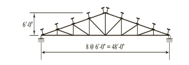
A truss with a roof system supporting a total gravity load of 40 psf of roof surface, half dead load and half snow. Spacing = 10 ft on centers.
Calculation:
Let’s calculate the nominal flexural strength about the X and Y axes.
Determine the strong axis bending strength. As neither the beam design charts nor the Z tables include shapes under W8 compute the flexural strength of W 6 X12. As there is no foot note to indicate otherwise the shape is compact.
We need to determine what controls the lateral torsional buckling.
Computing the values of
Substitute the values from the AISC Manual as
Substitute the values from the AISC Manual as
Now calculate the plastic moment for the section, we have
Where,
Substitute the values from the ASIC manual, we have
Let’s compare the values
Which implies that the strength is governed by inelastic Lateral- Torsional Buckling.
Compute the nominal strength of beam using the equation given as follows:
Substitute the values from the ASIC manual, we have
For the Y − axis, there is no flange buckling since the shape is compact.
Calculate the flexural strength about y- axis as:
Where,
Now, calculating the plastic moment of section about minor principal axis as:
Substitute the values, we have
Calculate the flexural strength about y axis, we have
Checking the upper limit using the following :
Substitute the values, we have
As the inequality is satisfied then the its OK.
Now using the LRFD method.
Following equation must be satisfied in order to know adhere to AISC specifications.
Where,
Now we need to find the values to substitute them
Where,
Where,
Where
As it is been given that half of load is dead load and half is snow load.
Therefore, as per the given conditions
Where,
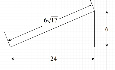
Following is the diagram from which we can find the value of angles.

Substitute the value for H = 6 ft and
Substitute the values
Substitute,
Find the flexural load about x-axis,
Similarly, for
Where,
Substitute,
Find the flexural load about x-axis,
Now, find the values of
As we have found every value, now we can substitute the values and check the adequacy
The equation is hence satisfied.
Conclusion:
Therefore, the beam is adequate.
(b)
The adequacy of W 6 X12 beam for use as purlin using ASD method.
Answer to Problem 5.5.16P
The beam is adequate to be used for purlin.
Explanation of Solution
Given:
A truss with a roof system supporting a total gravity load of 40 psf of roof surface, half dead load and half snow. Spacing = 10 ft on centers.

Calculation:
Now from Allowable stress design
Where
Now find the value of
Where,
Where,
Where
As it is been given that half of load is dead load and half is snow load.
Therefore, as per the given conditions
Calculate the load on the purlin as follows:
Following is the diagram from which we can find the value of angles.
Where,
Substitute the value for H = 6 ft and
Load on the purlin is as follows:
Substitute the values, we have
Now,
Where, L is the length of the beam and
Where,
Substitute the values, we have
Now find the value of
As we have found every value, now we can substitute the values and check the adequacy
Hence, the equation is satisfied.
Conclusion:
Therefore, the beam is adequate.
Want to see more full solutions like this?
Chapter 5 Solutions
Steel Design (Activate Learning with these NEW titles from Engineering!)

- W 14 x 142 is used as a column having a length of 9.21 m. long. It is hinged at the r end and fixed at the lower end but there is a lateral bracing perpendicular to minor axis of the W section at a point 3.52 m. above the bottom support. It is assumed to be pinned connected at the bracing point. Using A 36 steel Fy= 248 MPa the NSCP Specificatioris. E, = 200000 MPa. Properties of W 14 x 142 A = 26967.69 mm2 d= 374.65 mm bf= 393.70 mm tf= 27.00 mm tw= 17.27 mm4 Ix= 695.11 x 106 mm4 Iy = 274.71 x 106 mm4 rx = 160.53 mm rY = 100.84 mm Assume: Kx = 0.80 for 9.21 m. length KY = 1.9 for the length on the upper support KY = 0.80 for the length on the bottom support Compute the slenderness ratio along x-axis.arrow_forwardW 14 x 142 is used as a column having a length of 8.48 m. long. It is hinged at the r end and fixed at the lower end but there is a lateral bracing perpendicular to minor axis of the W section at a point 4.78 m. above the bottom support. It is assumed to be pinned connected at the bracing point. Using A 36 steel Fy= 248 MPa the NSCP Specificatioris. E, = 200000 MPa. Properties of W 14 x 142 A = 26967.69 mm2 d= 374.65 mm bf= 393.70 mm tf= 27.00 mm tw= 17.27 mm4 Ix= 695.11 x 106 mm4 Iy = 274.71 x 106 mm4 rx = 160.53 mm rY = 100.84 mm Assume: Kx = 0.80 for 8.48 m. length KY = 1.9 for the length on the upper support KY = 0.80 for the length on the bottom support Compute the slenderness ratio along y-axis. Please show clear solution thank youarrow_forwardDetermine the force of the members for the space truss shown in the figure. Joints A and B are supported by ball-and-socket while Joint C is supported by short link along z-axis. Indicate whether member is tension (T) or compression (C). 2m y Sm Az By BX Bz PAR Ax CSXScanned with Ca canner a SISU KN 15m 1 2117arrow_forward
- uestion 12 A W12x79 of AS73 Grade 60 (Fy - 415 MPa) steel is used as a compression member. It is 7.7 m long, fixed at the top and bottom, and has additional support in the weak direction at mid-height. Properties of the section are as follows: A- 14,500 mm^2 Ix = 258.6 x 1e*6 mm^4 Iy = 84.375 x 10^6 mm^4 Calculate the critical slenderness ratio with respect to weak axis buckling using theoretical value of k.arrow_forwardQ4: Calculate the forces induced in members KL, CL, and CB by the 20-ton load on the cantilever truss. M L. K 26 16' G E B A 6 panels at 12 20 tonsarrow_forwardThe truss shown is applied with service dead and service live loads as shown. Design with steel section for members AB and BD shown. Assume A e = Ag W 10 X not sufficient then use W 12 X sections. If W 10 X Fy = 50 ksi A B D 20¹ >< 201 PD = look PL = 175k X 20arrow_forward
- USE METHOD OF SECTION 2 k 2 k 2 k - 5 ft- 5 ft 5 ft- -5 ft A H F 5 ft C 03. FUND-PROB 037 PPeren Calculate forces in members GF, DG, CD for truss shown above.arrow_forwardE. With diagram/FBD Determine bar force member EFarrow_forwardDetermine the forces in each member of the truss. State wether it is in tension or compression. Draw a diagram of internal forces and present a results summary list. T a 446 a a a 12/2 커arrow_forward
- 2. Determine whether the compression member shown in Figure P4.3-7 is adequate to support the given service loads. a. Use LRFD. b. Use ASD. D = 560 kips L = 68 kips W12 × 79 A992 steel 20'arrow_forwardThe beam-column in Figure P6.5-6 is braced against sidesway. Bending is about the major axis, and A992 steel is used. The given loads are service loads, consisting of 25% dead load and 75% live load. Is this member adequate? a. Use LRFD. b. Use ASD. 190 k 80 ft-k W10 x 60 15' K, = K, = 1.0 75 ft-k 190 k FIGURE P6.5-6arrow_forwardQ2) The members of the truss structure shown below is plain concrete. The compressive strength of the concrete is 25 MPa. Compute the maximum load P that can be carried by the structure. (Cross section of each member of the truss is 200 x 200 mm and don't use material factors and do not consider slenderness) Comment on your results briefly. P A& 2m SC 2 m 1380 2m Darrow_forward
 Steel Design (Activate Learning with these NEW ti...Civil EngineeringISBN:9781337094740Author:Segui, William T.Publisher:Cengage Learning