Mechanics of Materials, 7th Edition
7th Edition
ISBN: 9780073398235
Author: Ferdinand P. Beer, E. Russell Johnston Jr., John T. DeWolf, David F. Mazurek
Publisher: McGraw-Hill Education
bartleby

Concept explainers

bartleby

Videos

Question
Book Icon
Chapter 4.9, Problem 149P

(a)

To determine

Find the value of θ for which the stress at D reaches its largest value.

(a)

Expert Solution
Check Mark

Answer to Problem 149P

The value of θ for which the stress at D reaches its largest value is 53.1°_.

Explanation of Solution

Given information:

The radius of the circular plate is R=125mm.

The width of the rectangular post is b=200mm and the height of the rectangular post is d=150mm.

The applied force is P=4kN.

Calculation:

Sketch the cross section of disk as shown in Figure 1.
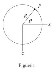
Mechanics of Materials, 7th Edition, Chapter 4.9, Problem 149P , additional homework tip  1

Refer to Figure 1.

Calculate the moment along x direction (Mx) as shown below.

Mx=PRsinθ

Substitute 4kN for P and 125mm for R.

Mx=4kN×1,000N1kN×125mm×1m1,000mm×sinθ=500sinθ

Calculate the moment along z direction (Mz) as shown below.

Mz=PRcosθ

Substitute 4kN for P and 125mm for R.

Mz=4kN×1,000N1kN×125mm×1m1,000mm×cosθ=500cosθ

Sketch the cross section of the rectangular post as shown in Figure 2.
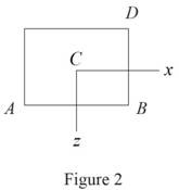
Mechanics of Materials, 7th Edition, Chapter 4.9, Problem 149P , additional homework tip  2

Refer to Figure 2.

Calculate the area (A) of the rectangular cross section as shown below.

A=bd

Substitute 200mm for b and 150mm for d.

A=200×150=30×103mm2×(1m1,000mm)2=30×103m2

Calculate the moment of inertia along x direction (Ix) as shown below.

Ix=bd312

Substitute 200mm for b and 150mm for d.

Ix=112×200×1503=56.25×106mm4×(1m1,000mm)4=56.25×10⁶m4

Calculate the moment of inertia along z direction (Iz) as shown below.

Iz=db312

Substitute 200mm for b and 150mm for d.

Iz=112×150×2003=100×106mm4×(1m1,000mm)4=100×106m4

The location of point D along x direction is xD=100mm.

The location of point D along z direction is zD=75mm.

Calculate the stress (σ) as shown below.

σ=PAMxzIx+MzxIz (1)

Substitute PRsinθ for Mx and PRcosθ for Mz.

σ=PA+PRsinθ×zIxPRcosθ×xIz=P(1A+RzsinθIxRxcosθIz)

The stress σ to be maximum, when dσdθ=0 with z=zD and x=xD.

Calculate the stress at point D (σD) as shown below.

Substitute zD for z and xD for x.

σD=P(1A+RzDsinθIxRxDcosθIz)

Calculate the value of θ as shown below.

Differentiate both sides of the Equation with respect to θ.

dσDdθ=P(0+RzDIx(cosθ)RxDIz(sinθ))=P(RzDcosθIx+RxDsinθIz)

Substitute 0 for dσDdθ.

P(RzDcosθIx+RxDsinθIz)=0RzDcosθIx=RxDsinθIzsinθcosθ=IzzDIxxDtanθ=IzzDIxxD

Substitute 100×106mm4 for Iz, 56.25×106mm4 for Ix, 75mm for zD, and 100mm for xD.

tanθ=100×106×(75)56.25×106×100=1.3333θ=tan1(1.3333)=53.1°

Therefore, the value of θ for which the stress at D reaches its largest value is 53.1°_.

(b)

To determine

Find the values of stress at A, B, C, and D.

(b)

Expert Solution
Check Mark

Answer to Problem 149P

The stress at A is σA=700kPa_.

The stress at B is σB=100kPa_.

The stress at C is σC=133.3kPa_.

The stress at D is σD=967kPa_.

Explanation of Solution

Given information:

The radius of the circular plate is R=125mm.

The width of the rectangular post is b=200mm and the height of the rectangular post is d=150mm.

The applied force is P=4kN.

Calculation:

Refer to part (a).

The value of θ for which the stress at D reaches its largest value is 53.1°.

The bending moment along x direction is Mx=500sinθ.

Substitute 53.1° for θ.

Mx=500sin53.1°=400Nm

The bending moment along z direction is Mz=500cosθ.

Substitute 53.1° for θ.

Mz=500cos53.1°=300Nm

Calculate the stress at A (σA) as shown below.

Refer to Figure 2 in part (a).

The location of point A along x direction is xA=100mm.

The location of point A along z direction is zA=75mm.

Substitute 4kN for P, 30×103mm2 for A, 56.25×106mm4 for Ix, 100×106mm4 for Iz, 100mm for xA, 75mm for zA, 400Nm for Mx, and 300Nm for Mz in Equation (1).

σA=(4kN×1,000N1kN30×103mm2(400Nm×1,000mm1m)×75mm56.25×106mm4+(300Nm×1,000mm1m)(100mm)100×106mm2)=0.1333+0.5333+0.3=0.7N/mm2×1,000kPa1N/mm2=700kPa

Hence, the stress at A is σA=700kPa_.

Calculate the stress at B (σB) as shown below.

Refer to Figure 2 in part (a).

The location of point B along x direction is xB=100mm.

The location of point B along z direction is zB=75mm.

Substitute 4kN for P, 30×103mm2 for A, 56.25×106mm4 for Ix, 100×106mm4 for Iz, 100mm for xB, 75mm for zB, 400Nm for Mx, and 300Nm for Mz in Equation (1).

σB=(4kN×1,000N1kN30×103mm2(400Nm×1,000mm1m)×75mm56.25×106mm4+(300Nm×1,000mm1m)×100mm100×106mm2)=0.1333+0.53330.3=0.1N/mm2×1,000kPa1N/mm2=100kPa

Hence, the stress at B is σB=100kPa_.

Calculate the stress at C (σC) as shown below.

Refer to Figure 2 in part (a).

The location of point C along x direction is xC=0.

The location of point C along z direction is zC=0.

Substitute 4kN for P, 30×103mm2 for A, 56.25×106mm4 for Ix, 100×106mm4 for Iz, 0 for xC, 0 for zC, 400Nm for Mx, and 300Nm for Mz in Equation (1).

σC=(4kN×1,000N1kN30×103mm2(400Nm×1,000mm1m)×056.25×106mm4+(300Nm×1,000mm1m)×0100×106mm2)=0.1333+0+=0.1333N/mm2×1,000kPa1N/mm2=133.3kPa

Hence, the stress at C is σC=133.3kPa_.

Calculate the stress at D (σD) as shown below.

Refer to Figure 2 in part (a).

The location of point D along x direction is xD=100mm.

The location of point D along z direction is zD=75mm.

Substitute 4kN for P, 30×103mm2 for A, 56.25×106mm4 for Ix, 100×106mm4 for Iz, 100mm for xD, 75mm for zD, 400Nm for Mx, and 300Nm for Mz in Equation (1).

σD=(4kN×1,000N1kN30×103mm2(400Nm×1,000mm1m)×(75mm)56.25×106mm4+(300Nm×1,000mm1m)×100mm100×106mm2)=0.13330.53330.3=0.9666N/mm2×1,000kPa1N/mm2=967kPa

Therefore, the stress at D is σD=967kPa_.

Want to see more full solutions like this?

Subscribe now to access step-by-step solutions to millions of textbook problems written by subject matter experts!
Students have asked these similar questions
The four forces shown are applied to a rigid plate supported by a solid steel post of radius a. Knowing that P= 24 kips and a= 1.6 in., determine the maximum stress in the post when (a) the force at D is removed, (b) the forces at C and D are removed
2.36 A 250-mm bar of 150 x 30-mm rectangular cross section consists of two aluminum layers, 5 mm thick, brazed to a center brass layer of the same thickness. If it is subjected to centric forces of magni- tude P = 30 kN, and knowing that E, = 70 GPa and E, = 105 GPa, determine the normal stress (a) in the aluminum layers, (b) in the brass layer. P' 250 mm 5 mm 5 mm 5 mm Aluminum Brass Aluminum P 30 mm Fig. P2.36
18 mm) B 40 mm PROBLEM 4.106 Knowing that the allowable stress in section ABD is 80 MPa, determine the largest force P that can be applied to the bracket shown. 12 mm 12 mm

Chapter 4 Solutions

Mechanics of Materials, 7th Edition

Ch. 4.3 - 4.9 through 4.11 Two vertical forces are applied...Ch. 4.3 - Knowing that a beam of the cross section shown is...Ch. 4.3 - Knowing that a beam of the cross section shown is...Ch. 4.3 - Solve Prob. 4.13, assuming that the beam is bent...Ch. 4.3 - Knowing that for the extruded beam shown the...Ch. 4.3 - The beam shown is made of a nylon for which the...Ch. 4.3 - Solve Prob. 4.16, assuming that d = 40 mm.Ch. 4.3 - Knowing that for the beam shown the allowable...Ch. 4.3 - 4.19 and 4.20 Knowing that for the extruded beam...Ch. 4.3 - 4.19 and 4.20 Knowing that for the extruded beam...Ch. 4.3 - Straight rods of 6-mm diameter and 30-m length are...Ch. 4.3 - A 900-mm strip of steel is bent into a full circle...Ch. 4.3 - Straight rods of 0.30-in. diameter and 200-ft...Ch. 4.3 - A 60-Nm couple is applied to the steel bar shown,...Ch. 4.3 - (a) Using an allowable stress of 120 MPa,...Ch. 4.3 - A thick-walled pipe is bent about a horizontal...Ch. 4.3 - A couple M will be applied to a beam of...Ch. 4.3 - A portion of a square bar is removed by milling,...Ch. 4.3 - In Prob. 4.28, determine (a) the value of h for...Ch. 4.3 - For the bar and loading of Concept Application...Ch. 4.3 - Prob. 31PCh. 4.3 - It was assumed in Sec. 4.1B that the normal...Ch. 4.5 - 4.33 and 4.34 A bar having the cross section shown...Ch. 4.5 - 4.33 and 4.34 A bar having the cross section shown...Ch. 4.5 - 4.35 and 4.36 For the composite bar indicated,...Ch. 4.5 - Prob. 36PCh. 4.5 - 4.37 and 4.38 Wooden beams and steel plates are...Ch. 4.5 - 4.37 and 4.38 Wooden beams and steel plates are...Ch. 4.5 - 4.39 and 4.40 A copper strip (Ec = 105 GPa) and an...Ch. 4.5 - 4.39 and 4.40 A copper strip (Ec = 105 GPa) and an...Ch. 4.5 - 4.41 and 4.42 The 6 12-in. timber beam has been...Ch. 4.5 - 4.41 and 4.42 The 6 12-in. timber beam has been...Ch. 4.5 - 4.43 and 4.44 For the composite beam indicated,...Ch. 4.5 - Prob. 44PCh. 4.5 - Prob. 45PCh. 4.5 - Prob. 46PCh. 4.5 - A concrete slab is reinforced by 58-in.-diameter...Ch. 4.5 - Solve Prob. 4.47, assuming that the spacing of the...Ch. 4.5 - The reinforced concrete beam shown is subjected to...Ch. 4.5 - Prob. 50PCh. 4.5 - Knowing that the bending moment in the reinforced...Ch. 4.5 - A concrete beam is reinforced by three steel rods...Ch. 4.5 - The design of a reinforced concrete beam is said...Ch. 4.5 - For the concrete beam shown, the modulus of...Ch. 4.5 - 4.55 and 4.56 Five metal strips, each 0.5 1.5-in....Ch. 4.5 - 4.55 and 4.56 Five metal strips, each 0.5 1.5-in....Ch. 4.5 - The composite beam shown is formed by bonding...Ch. 4.5 - A steel pipe and an aluminum pipe are securely...Ch. 4.5 - The rectangular beam shown is made of a plastic...Ch. 4.5 - Prob. 60PCh. 4.5 - Knowing that M = 250 Nm, determine the maximum...Ch. 4.5 - Knowing that the allowable stress for the beam...Ch. 4.5 - Semicircular grooves of radius r must be milled as...Ch. 4.5 - Prob. 64PCh. 4.5 - A couple of moment M = 2 kNm is to be applied to...Ch. 4.5 - The allowable stress used in the design of a steel...Ch. 4.6 - The prismatic bar shown is made of a steel that is...Ch. 4.6 - Prob. 68PCh. 4.6 - Prob. 69PCh. 4.6 - Prob. 70PCh. 4.6 - The prismatic rod shown is made of a steel that is...Ch. 4.6 - Solve Prob. 4.71, assuming that the couples M and...Ch. 4.6 - 4.73 and 4.74 A beam of the cross section shown is...Ch. 4.6 - 4.73 and 4.74 A beam of the cross section shown is...Ch. 4.6 - 4.75 and 4.76 A beam of the cross section shown is...Ch. 4.6 - Prob. 76PCh. 4.6 - 4.77 through 4.80 For the beam indicated,...Ch. 4.6 - Prob. 78PCh. 4.6 - Prob. 79PCh. 4.6 - 4.77 through 4.80 For the beam indicated,...Ch. 4.6 - 4.81 through 4.83 Determine the plastic moment Mp...Ch. 4.6 - Prob. 82PCh. 4.6 - Prob. 83PCh. 4.6 - Determine the plastic moment Mp of a steel beam of...Ch. 4.6 - Determine the plastic moment Mp of the cross...Ch. 4.6 - Determine the plastic moment Mp of a steel beam of...Ch. 4.6 - Prob. 87PCh. 4.6 - Prob. 88PCh. 4.6 - Prob. 89PCh. 4.6 - Prob. 90PCh. 4.6 - Prob. 91PCh. 4.6 - Prob. 92PCh. 4.6 - Prob. 93PCh. 4.6 - Prob. 94PCh. 4.6 - Prob. 95PCh. 4.6 - Prob. 96PCh. 4.6 - Prob. 97PCh. 4.6 - Prob. 98PCh. 4.7 - Knowing that the magnitude of the horizontal force...Ch. 4.7 - A short wooden post supports a 6-kip axial load as...Ch. 4.7 - Two forces P can be applied separately or at the...Ch. 4.7 - A short 120 180-mm column supports the three...Ch. 4.7 - As many as three axial loads, each of magnitude P...Ch. 4.7 - Two 10-kN forces are applied to a 20 60-mm...Ch. 4.7 - Portions of a 1212-in. square bar have been bent...Ch. 4.7 - Knowing that the allowable stress in section ABD...Ch. 4.7 - A milling operation was used to remove a portion...Ch. 4.7 - A milling operation was used to remove a portion...Ch. 4.7 - The two forces shown are applied to a rigid plate...Ch. 4.7 - Prob. 110PCh. 4.7 - Prob. 111PCh. 4.7 - A short column is made by nailing four 1 4-in....Ch. 4.7 - A vertical rod is attached at point A to the cast...Ch. 4.7 - A vertical rod is attached at point A to the cast...Ch. 4.7 - Knowing that the clamp shown has been tightened...Ch. 4.7 - Prob. 116PCh. 4.7 - Three steel plates, each of 25 150-mm cross...Ch. 4.7 - A vertical force P of magnitude 20 kips is applied...Ch. 4.7 - The four bars shown have the same cross-sectional...Ch. 4.7 - Prob. 120PCh. 4.7 - An eccentric force P is applied as shown to a...Ch. 4.7 - Prob. 122PCh. 4.7 - Prob. 123PCh. 4.7 - Prob. 124PCh. 4.7 - A single vertical force P is applied to a short...Ch. 4.7 - The eccentric axial force P acts at point D, which...Ch. 4.9 - 4.127 through 4.134 The couple M is applied to a...Ch. 4.9 - 4.127 through 4.134 The couple M is applied to a...Ch. 4.9 - 4.127 through 4.134 The couple M is applied to a...Ch. 4.9 - 4.127 through 4.134 The couple M is applied to a...Ch. 4.9 - 4.127 through 4.134 The couple M is applied to a...Ch. 4.9 - 4.127 through 4.134 The couple M is applied to a...Ch. 4.9 - Prob. 133PCh. 4.9 - Prob. 134PCh. 4.9 - 4.135 through 4.140 The couple M acts in a...Ch. 4.9 - 4.135 through 4.140 The couple M acts in a...Ch. 4.9 - Prob. 137PCh. 4.9 - 4.135 through 4.140 The couple M acts in a...Ch. 4.9 - 4.135 through 44.140 The couple M acts in a...Ch. 4.9 - 4.135 through 4.140 The couple M acts in a...Ch. 4.9 - Prob. 141PCh. 4.9 - 4.141 through 4.143 The couple M acts in a...Ch. 4.9 - 4.141 through 4.143 The couple M acts in a...Ch. 4.9 - The tube shown has a uniform wall thickness of 12...Ch. 4.9 - Prob. 145PCh. 4.9 - Knowing that P = 90 kips, determine the largest...Ch. 4.9 - Knowing that a = 1.25 in., determine the largest...Ch. 4.9 - A rigid circular plate of 125-mm radius is...Ch. 4.9 - Prob. 149PCh. 4.9 - A beam having the cross section shown is subjected...Ch. 4.9 - Prob. 151PCh. 4.9 - Prob. 152PCh. 4.9 - Prob. 153PCh. 4.9 - Prob. 154PCh. 4.9 - Prob. 155PCh. 4.9 - Prob. 156PCh. 4.9 - Prob. 157PCh. 4.9 - Prob. 158PCh. 4.9 - A beam of unsymmetric cross section is subjected...Ch. 4.9 - Prob. 160PCh. 4.10 - For the curved bar shown, determine the stress at...Ch. 4.10 - For the curved bar shown, determine the stress at...Ch. 4.10 - Prob. 163PCh. 4.10 - Prob. 164PCh. 4.10 - The curved bar shown has a cross section of 40 60...Ch. 4.10 - Prob. 166PCh. 4.10 - Prob. 167PCh. 4.10 - Prob. 168PCh. 4.10 - The curved bar shown has a cross section of 30 30...Ch. 4.10 - Prob. 170PCh. 4.10 - Prob. 171PCh. 4.10 - Three plates are welded together to form the...Ch. 4.10 - 4.173 and 4.174 Knowing that the maximum allowable...Ch. 4.10 - Prob. 174PCh. 4.10 - Prob. 175PCh. 4.10 - Prob. 176PCh. 4.10 - Prob. 177PCh. 4.10 - Prob. 178PCh. 4.10 - Prob. 179PCh. 4.10 - Knowing that P = 10 kN, determine the stress at...Ch. 4.10 - Prob. 181PCh. 4.10 - Prob. 182PCh. 4.10 - Prob. 183PCh. 4.10 - Prob. 184PCh. 4.10 - Prob. 185PCh. 4.10 - Prob. 186PCh. 4.10 - Prob. 187PCh. 4.10 - Prob. 188PCh. 4.10 - Prob. 189PCh. 4.10 - Prob. 190PCh. 4.10 - For a curved bar of rectagular cross section...Ch. 4 - Two vertical forces are applied to a beam of the...Ch. 4 - Prob. 193RPCh. 4 - Prob. 194RPCh. 4 - Determine the plastic moment Mp of a steel beam of...Ch. 4 - In order to increase corrosion resistance, a...Ch. 4 - The vertical portion of the press shown consists...Ch. 4 - The four forces shown are applied to a rigid plate...Ch. 4 - Prob. 199RPCh. 4 - Prob. 200RPCh. 4 - Three 120 10-mm steel plates have been welded...Ch. 4 - A short length of a W8 31 rolled-steel shape...Ch. 4 - Two thin strips of the same material and same...
Knowledge Booster
Background pattern image
Mechanical Engineering
Learn more about
Need a deep-dive on the concept behind this application? Look no further. Learn more about this topic, mechanical-engineering and related others by exploring similar questions and additional content below.
Similar questions
SEE MORE QUESTIONS
Recommended textbooks for you
Text book image
Elements Of Electromagnetics
Mechanical Engineering
ISBN:9780190698614
Author:Sadiku, Matthew N. O.
Publisher:Oxford University Press
Text book image
Mechanics of Materials (10th Edition)
Mechanical Engineering
ISBN:9780134319650
Author:Russell C. Hibbeler
Publisher:PEARSON
Text book image
Thermodynamics: An Engineering Approach
Mechanical Engineering
ISBN:9781259822674
Author:Yunus A. Cengel Dr., Michael A. Boles
Publisher:McGraw-Hill Education
Text book image
Control Systems Engineering
Mechanical Engineering
ISBN:9781118170519
Author:Norman S. Nise
Publisher:WILEY
Text book image
Mechanics of Materials (MindTap Course List)
Mechanical Engineering
ISBN:9781337093347
Author:Barry J. Goodno, James M. Gere
Publisher:Cengage Learning
Text book image
Engineering Mechanics: Statics
Mechanical Engineering
ISBN:9781118807330
Author:James L. Meriam, L. G. Kraige, J. N. Bolton
Publisher:WILEY
Pressure Vessels Introduction; Author: Engineering and Design Solutions;https://www.youtube.com/watch?v=Z1J97IpFc2k;License: Standard youtube license