
Concept explainers
Videos
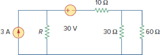
Consider the 30-Ω resistor in Fig. 4.134. First compute the Thevenin equivalent circuit as seen by the 30-Ω resistor. Compute the value of R that results in Thevenin equivalent resistance equal to the 30-Ω resistance and then calculate power delivered to the 30-Ω resistor. Now let R = 0 Ω, 110 Ω, and ∞, calculate the power delivered to the 30-Ω resistor in each case. What can you say about the value of R that will result in the maximum power that can be delivered to the 30-Ω resistor?
Figure 4.134
Find the Thevenin equivalent seen by the
Calculate the power delivered to the
Answer to Problem 68P
The Thevenin voltage is
The power delivered to the
Explanation of Solution
Given data:
Refer to Figure 4.134 in the textbook.
The current source is
The voltage source is
The Thevenin resistance
Calculation:
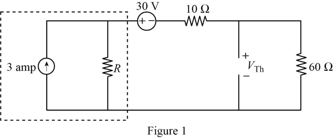
In the given circuit, find the Thevenin voltage by removing the 30 ohms resistor and the modified circuit is shown in Figure 1.
The modified circuit is shown in Figure 1.
In Figure 1, the current source with parallel resistance is converted into voltage source with series resistance using source transformation. The voltage V is calculated by using ohms law as follows,
The source transformation is shown in Figure 2.
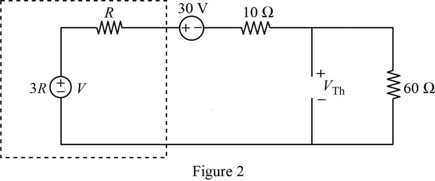
In Figure 2, the Thevenin voltage is,
Refer to Figure 4.134 in the textbook.
In the given circuit, find the Thevenin resistance by turning off the
The modified circuit is shown in Figure 3.
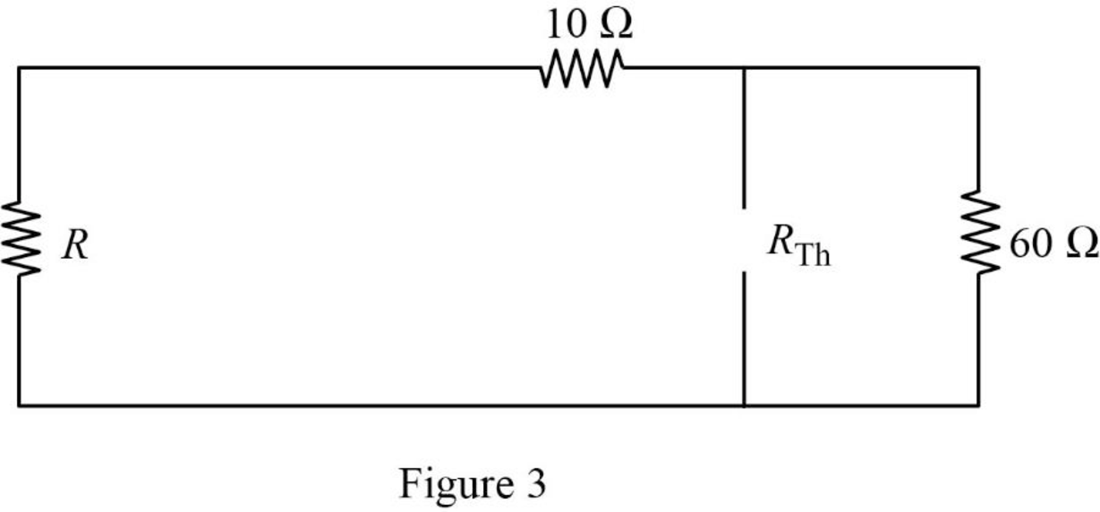
In Figure 3, the Thevenin resistance is,
Substitute
Substitute 50 for R in equation (1) to find the Thevenin voltage in volts.
Substitute 50 for R in equation (2) to find the Thevenin resistance in ohms.
The Thevenin equivalent connected to the 30 ohms resistor is shown in Figure 4.
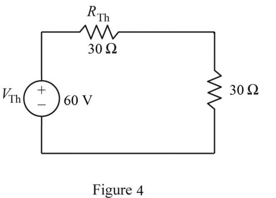
The power delivered to the 30 ohms resistor is,
Substitute 60 for
Consider the resistance
When
Substitute 0 for R in equation (2) to find the Thevenin resistance in ohms.
When
Substitute 0 for R in equation (1) to find the Thevenin voltage in volts.
When
Substitute
Consider the resistance
When
Substitute 110 for R in equation (2) to find the Thevenin resistance in ohms.
When
Substitute 110 for R in equation (1) to find the Thevenin voltage in volts.
When
Substitute
Consider the resistance
When
Simplify equation (2) as follows,
Substitute
When
Simplify equation (1) as follows,
Substitute
When
Substitute
Thus, when
Conclusion:
Thus, the Thevenin voltage is
The power delivered to the
Want to see more full solutions like this?
Chapter 4 Solutions
Fundamentals of Electric Circuits


- Problem 4.4: Design a voltage divider circuit that provides 3.3 V across one resistor. The voltage source is an array of solar cells that provide 4.6 V. What two resistor values will you choose? The following resistors are available: 330 N, 390 N, 450 2, 510 Q, and 1,000 Q.arrow_forwardQ4: Find Rab for the circuit in figure below 20 Ω ww 16 2 a ww 20Ω 18Ω Rab 12 ww ww wwarrow_forwardUsing only source transformation and without eliminating ix, reduce the circuit in Figure to a single voltage source and a single resistor, then obtain ix using Ohm's law. Please answer the 2 questions A) What is the value of the source voltage in V and what is the value of the resistor in Ω? B) What is the value of ix in Amps?arrow_forward
- If we want to connect a voltage source with two resistors (either in series or in parallel) then voltage drop across the resistor R1 and the voltage across the resistor R2 ( if R1= R,= 10N) will be the same whether they are connected in series or in parallel. Select one: O True False < o Oarrow_forwardSUPERPOSITION THEOREM ACTIVITY Find the current through the 5 ohms, 6 ohms and 3 ohms resistors. Also find the voltage drop across the three resistors. Use the superposition theorem in solving the currents and voltages. S thr 6Ω ww + 20 V 40 V www.elecrically4u.comarrow_forwardConsider the circuit in figure 4. a) Isolate RL and draw the Thevenin Equivalent circuit at terminals a-b. 4Vx a b) From part (a), reconnect and determine the value of R which absorbs the maximum power. c) Find this maximum power if I, is 9A. Vx+ 2 AMarrow_forward
- circu giver given Circuit Theory methods and find the voltage between node A and ground. R,=60 R-40 R,=10 R,=10 v,=150 V R=15 R-50 R,=30 R1,=40- D1=10 A A B R,=25 R=20 v,=250 V wwarrow_forwardApplying transformation of successive sources, obtain the circuit that allows to calculate the voltage drop in R1, by voltage dividers and calculate its value.arrow_forward:Q1(6*1)/For the circuit shown in the figure below, using nodal analysis to find 2 S 8 S ww V3 2 A IS 4 S 13 V ww wwarrow_forward
- (True/False) It is safe to connect a 2002 resistor rated at 3/4W in parallel with a 10V source rated 10W. Select one: O True O Falsearrow_forwardQ4(a) For the circuit shown in Figure Q4 (a), find the Thevenin equivalent with respect to terminals "a-b". 2 A 20 Ω ww 120 V 40 2 12 2 Figure Q4 (a) wwarrow_forwardQ4: Obtain the Thevenin equivalent circuit at terminals a-b for the circuit in figure shown below: 5 A 10% + 10 492 292 www-oa barrow_forward
 Introductory Circuit Analysis (13th Edition)Electrical EngineeringISBN:9780133923605Author:Robert L. BoylestadPublisher:PEARSON
 Delmar's Standard Textbook Of ElectricityElectrical EngineeringISBN:9781337900348Author:Stephen L. HermanPublisher:Cengage Learning
 Programmable Logic ControllersElectrical EngineeringISBN:9780073373843Author:Frank D. PetruzellaPublisher:McGraw-Hill Education
 Fundamentals of Electric CircuitsElectrical EngineeringISBN:9780078028229Author:Charles K Alexander, Matthew SadikuPublisher:McGraw-Hill Education
 Electric Circuits. (11th Edition)Electrical EngineeringISBN:9780134746968Author:James W. Nilsson, Susan RiedelPublisher:PEARSON
 Engineering ElectromagneticsElectrical EngineeringISBN:9780078028151Author:Hayt, William H. (william Hart), Jr, BUCK, John A.Publisher:Mcgraw-hill Education,