
Applied Statics and Strength of Materials (6th Edition)
6th Edition
ISBN: 9780133840544
Author: George F. Limbrunner, Craig D'Allaird, Leonard Spiegel
Publisher: PEARSON
expand_more
expand_more
format_list_bulleted
Concept explainers
Videos
Textbook Question
Chapter 4, Problem 4.33CP
For the following computer problems, any appropriate software may be used. Input prompts should fully explain what required of the user (the program should be user-friendly). The resulting output should be well labeled and self-explanatory.
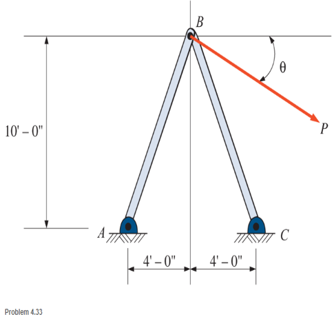
4.33 Write a program that will calculate the forces in members AB and CB for the support frame shown. User input is to be θ and P (where
Expert Solution & Answer
Want to see the full answer?
Check out a sample textbook solution
Students have asked these similar questions
Please help. Please make sure you clearly state how you got the numbers you got and why you are using them. Also please make sure you clearly put your formulas and label your units along the numbers that you are using.
In the following frame ilustration, F1s 60 N and F2 is 9 N. What is the tension in the cable AB and the reaction force vector necessary to keep the system in static equilibrium? Give the X component reaction force at C( for an x axis going left to right). Also please solve for the rest of the 3 unknowns please.
Thank you
A truss is facing a two-force member and both of them are in the opposite directions, and the truss is in
equilibrium. And both of them are coming to each other. The forces are called
Select one:
O a. Tensile Forces
O b. Compressive forces
O c Parallel and collinear forces with same direction of heading
O d. The rotational forces
Next page
est-3
Jump to...
The force vector F has a magnitude of F = 385 lb and acts at
point A at an angle 0 = 17.8° with respect to vertical as
shown. The force F is balanced by the tension forces parallel
to the two rods AC and AB such that the vector equation
F+FAC+ FAB = 0 is satisfied. Determine the tension
forces in the two rods in Cartesian components.
C
mintono
cc) + Ⓡ
BY NC SA
2013 Michael Swanbom
Variable Value
4.6 ft
2.7 ft
4 ft
a
b
C
FAB
F
Values for dimensions on the figure are given in the following
table. Note the figure may not be to scale.
FAC=
a
=
For the component notation, use an 'xy' coordinate system with
'y' poining up and 'x' pointing to the right.
î
A
+
0
+
b
B
3) lb
3) lb
Chapter 4 Solutions
Applied Statics and Strength of Materials (6th Edition)
Ch. 4 - and 4.2 Sketch free-body diagram for the members...Ch. 4 - Sketch free-body diagram for the members shown.Ch. 4 - A steel cylinder having a mass of 120 kgis...Ch. 4 - A 50-lb block is supported by a pin support and a...Ch. 4 - A cylinder weighing 200 lb is supported on an...Ch. 4 - A weight W is supported by a flexible cable and an...Ch. 4 - The ladder shown is supported by a smooth...Ch. 4 - What horizontal force F applied at the center of...Ch. 4 - Calculate the force in cable AB and the angle (...Ch. 4 - Calculate the horizontal force F that should be...
Ch. 4 - Calculate the reactions of the two smooth inclined...Ch. 4 - Calculate the force in each cable for the...Ch. 4 - Three members of a truss intersect at joint B as...Ch. 4 - Four concurrent forces in equilibrium act at point...Ch. 4 - The beam shown carries vertical concentrated...Ch. 4 - Find the reactions at A and B for the beam shown....Ch. 4 - A simply supported beam spans 10 m. The beam...Ch. 4 - The beam shown carries vertical loads. Calculate...Ch. 4 - Calculate the reaction at each support for the...Ch. 4 - Calculate the reactions at A and B for the beam...Ch. 4 - Calculate the reactions at A and B for the beam...Ch. 4 - A 12-ft simple beam is supported at each end. It...Ch. 4 - The beam shown carries vertical loads as...Ch. 4 - Determine the reactions for the beam shown. The...Ch. 4 - Calculate the reaction at each support for the...Ch. 4 - Calculate the wall reactions for the cantilever...Ch. 4 - Determine the reactions at supports A and B of the...Ch. 4 - A mass M of 300 kg is supported by a boom, as...Ch. 4 - Rework Problem 4.28 assuming that point D has been...Ch. 4 - Calculate the force in the tie rod BC and the...Ch. 4 - The davit shown is used in pairs for...Ch. 4 - For the following computer problems, any...Ch. 4 - For the following computer problems, any...Ch. 4 - For the following computer problems, any...Ch. 4 - For the structure shown, draw free-body diagram...Ch. 4 - A 1200-lb load is supported by a cable that runs...Ch. 4 - For the pin-connected frame shown, sketch a...Ch. 4 - For the concurrent force system shown, calculate...Ch. 4 - A strut having a mass of 40 kg/m is supported by a...Ch. 4 - Calculate the reaction at each support for the...Ch. 4 - Calculate the reaction at each support for the...Ch. 4 - A beam supports a nonuniformly distributed load as...Ch. 4 - Calculate the reactions at each support for the...Ch. 4 - Compute reactions at each support for the beam...Ch. 4 - A rod of uniform cross section weighs 4 lb/ft and...Ch. 4 - A 12-ft-long weightiness member supports two...Ch. 4 - A uniform rod AB, having a weight of 5.00 lb and a...Ch. 4 - The plastic barrel tent anchor of Problem 2.11...Ch. 4 - Compute the reactions at A and B for the bracket...Ch. 4 - The truss shown is supported by a pin at A and a...Ch. 4 - Find the reactions at supports A and B for the...Ch. 4 - Find the reactions at supports A and B for the...Ch. 4 - Determine the reactions at A and B for the truss...Ch. 4 - A 40-ft ladder weighing 130 lb is pin-connected to...Ch. 4 - The frame shown is pin-connected at point A and...Ch. 4 - Prob. 4.56SPCh. 4 - A horizontal beam is pin-connected to a wall at...Ch. 4 - Calculate the force in the cable for the structure...Ch. 4 - The Thenard shutter dam shown was originally...Ch. 4 - An inclined railway can be used to lift heavy...Ch. 4 - Two cylinders are supported in a box, as shown....
Knowledge Booster


Learn more about
Need a deep-dive on the concept behind this application? Look no further. Learn more about this topic, mechanical-engineering and related others by exploring similar questions and additional content below.Similar questions
- A weight W= 120 kN is being supported by steel sections with force T, force F, andforce C. The coordinates of A, B, C, and D are given. Assume that E is the origin(0,0,0). Determine Forces T, F, and C. (Hint: Produce three equations fromequilibrium of force system)Note: The Forces T, F, and C must be computed accurately to design the proper sizes ofsteel sections in the subject “Steel Design.”arrow_forwardA FBD should include the isolated system and only the known forcesand moments. false O truearrow_forwardFind: 1, The magnitude of the horizontal component of the reaction force at Support-A is The magnitude of the vertical component of the reaction force at Support-A is The magnitude of the horizontal component of the reaction force at Support-B is The magnitude of the vertical component of the reaction force at Support-B is 5. The magnitude of the horizontal component of the force carried by Pin-C is 6. The magnitude of the vertical component of the force carried by Pin-C is mm 200 4. 2. 3. 3 kN Hinge 400 mm C 12.5 kN/m 400 mm KN. KN. kN. kN. kN. KN.arrow_forward
- The bent rod of negligible weight is supported by the ball-and-socket joint at B and the cables attached to points A and C. Find the forces in the cables and the magnitude of the reaction at B. Dimensions Figure P.5.39arrow_forwardFind the internal force systems acting on sections 1 and 2.arrow_forwardThe structure is supported by a pin at C and a cable attached to A. The cable runs over the small pulley D. Find the internal force systems acting on sections 1 and 2.arrow_forward
- I. Solve the following problems completely: Show your complete solution and draw the graph. 1. Locate, and find the magnitude and the position of the resultant R at point A of the forces acting on the Fink Truss shown in the figure. Find the couple at point B. Given Figure: 250N 30⁰ 350N 8m 60% 4m 450N 2100N 8m 8m 60⁰ 8m 60% 350N 4m 60⁰ 30⁰ 8m 250N Barrow_forward) Three cables are secured to a ring at B. A turnbuckle on cable BC is tightened such that the tension in cable BC is 1.6 kN. (Hint: You’ll need to define/insert your own x-y coordinate system). Determine the tensions in cables BA and BD. (Hint: FBD/EQNS/SOLVE)arrow_forwardThe following forces are acting on the bracket below (a free-body diagram of the bracket is shown), that is hinged at point 1 (bottom left point). The bracket is in equilibrium (not accelerating). The force at point 2 must act horizontally, but can act to the right or left. I drew the force acting at point 2 (the middle point) pushing the bracket to the right. For the given forces, did I draw the force acting on the bracket in the correct direction? F2 F1x 10 Ibf Yes No Can't be determined based on the given informationarrow_forward
- Problem1 The rigid body shown below (Fig 1) is subjected to four cable forces applied at different points A, B, and C. (a) Determine an equivalent system consisting of a Force-Couple system at point O. (b) Determine an equivalent force system consisting of a Single Force and specify the y-coordinate of the point where its line of action intersects the y-axis. (c) Show the resultant force in a separate graph.\ Un assemblage soudé est une structure (un corps rigide) construite en soudant un assemblage de pièces ensemble. L'assemblage soudé illustré ci-dessous (Fig. 1) est soumis à quatre forces de câble. (a) Déterminer un système équivalent consistant en un système Force-Couple au point O (b) Déterminer un système équivalent constitué d'une Force Unique et spécifiez la coordonnée y du point où sa ligne d'action coupe l'axe y. (c) Afficher la force résultante dans un graphique séparé Fig.1 0.5kN 0.4kN 0.6kN 45° B 1.2m 0.3kN 0.3m 0.9m 0.8m 1arrow_forwardReferring to the force system shown: a. Draw the free body diagram of the force system and identify the forces involved in the problem. b. Setup the equations to solve the problem. c. Compute the tensile force in each cord. B A | 105° 90 30 30 75° 300 lb 400 lbarrow_forwardAnswer the following question: 4. Find the forces at points A and B of the landing gear shown.arrow_forward
arrow_back_ios
SEE MORE QUESTIONS
arrow_forward_ios
Recommended textbooks for you
 International Edition---engineering Mechanics: St...Mechanical EngineeringISBN:9781305501607Author:Andrew Pytel And Jaan KiusalaasPublisher:CENGAGE L
International Edition---engineering Mechanics: St...
Mechanical Engineering
ISBN:9781305501607
Author:Andrew Pytel And Jaan Kiusalaas
Publisher:CENGAGE L
Types Of loads - Engineering Mechanics | Abhishek Explained; Author: Prime Course;https://www.youtube.com/watch?v=4JVoL9wb5yM;License: Standard YouTube License, CC-BY