
Videos
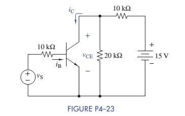
The parameters of the transistor in Figure P4-23 are
Want to see the full answer?
Check out a sample textbook solution
Chapter 4 Solutions
ANALYSIS+DESIGN OF LINEAR CIRCUITS(LL)
Additional Engineering Textbook Solutions
Electric Circuits (10th Edition)
Basic Engineering Circuit Analysis
Fundamentals of Applied Electromagnetics (7th Edition)
Electric Circuits. (11th Edition)
Electrical Engineering: Principles & Applications (7th Edition)
Introductory Circuit Analysis (13th Edition)


- T1 12v 6v A 4.5v 3v To Diode circuit Ov common B D1 A C1 RL 1B4B42 1000µF 3kQ Find the output voltage across the load RL VL output current through RL and the power dissipated by RL for the following input voltages 3v,4.5v, 6v,9v &12arrow_forwardReset WED W=O W =l EhD DII W=0 Derive the following state-table Present state Next state output z2zlz0 W=0 W=1 A 000 B 001 C 010 D 011 E 100arrow_forwardQ4) what is the wrong of the following instructions a) MOV DS, SS b) MOV CL, CS c) OUT AX, CLarrow_forward
- Determine the regulated output voltage of the circuit in Figure D IN4O02 Vour LM317 R 2402 D2 ADI IN4002 120 V ms 470uF 1.8 kQ 000arrow_forward2.0 a. TMP35 b. TMP36 c. TMP37 +Vs - 3V Using the appropriate curve, develop a linear equation for the output temperature as a function of voltage. 1.8 1.6 E 1.4 1.2 1.0 0.8 0.6 0.4 0.2 -50 -25 25 50 75 100 125 TEMPERATURE (*C) Figure 6. Output Voltage vs. Temperature OUTPUT VOLTAGE (V) 200-20C 00arrow_forwardVoltage Zener is used in the circuit below and the load current is to vary from 12 to 100 mA. Find the value of series resistance R and the range of load resistance to maintain a voltage of 7.2 V across the load. The input voltage is constant at 12V and the minimum Zener current is 10 mA. ... IL R Iz Eo RL Vz E, = 12 Varrow_forward
- Q2. A Speedo meter has a static error of 2 RPM with an accuracy of 98.12%, then calculate the following. i. True Value ) ii. % Errorarrow_forwardT1 12v Gv A 4.5v 3v To Diode circuit Ov common B D1 A C1 1000µF RL 3kQ 1B4B42 Find the output voltage across the load RL VL output current through RL and the power dissipated by RL for the following input voltages 3v.4.5v,6v,9v & 12arrow_forwardWhat is the value of r4arrow_forward
- Consider a PV Module with 4 solar PV cells with the Size of each 10cm x 10cm are connected in Parallel. If we connect a lamp load of 2W across this module, choose the correct statement for the above PV Module. (Assume necessary data) a. The output voltage is 0.5V, the output current is 2A b. The output voltage is 0.5V, the output current is 4A c. The output voltage is 2V, the output current is 2A d. The output voltage is 2V, the output current is 4Aarrow_forwardbasic electronis please give full answer thanks Given Sketch the drain and transconductance curve for VGS = +2V, +1V, 0V -1V, -2V, -3V and -4V.arrow_forwardV Dp Figure 1 V DD d|M2 M6 CLK –d|M4 CLK - |Mg D CLK –|M3 CLK –|M7 QM M1 M5 Master Stage Slave Stagearrow_forward
 Introductory Circuit Analysis (13th Edition)Electrical EngineeringISBN:9780133923605Author:Robert L. BoylestadPublisher:PEARSON
 Delmar's Standard Textbook Of ElectricityElectrical EngineeringISBN:9781337900348Author:Stephen L. HermanPublisher:Cengage Learning
 Programmable Logic ControllersElectrical EngineeringISBN:9780073373843Author:Frank D. PetruzellaPublisher:McGraw-Hill Education
 Fundamentals of Electric CircuitsElectrical EngineeringISBN:9780078028229Author:Charles K Alexander, Matthew SadikuPublisher:McGraw-Hill Education
 Electric Circuits. (11th Edition)Electrical EngineeringISBN:9780134746968Author:James W. Nilsson, Susan RiedelPublisher:PEARSON
 Engineering ElectromagneticsElectrical EngineeringISBN:9780078028151Author:Hayt, William H. (william Hart), Jr, BUCK, John A.Publisher:Mcgraw-hill Education,