
Concept explainers
Videos
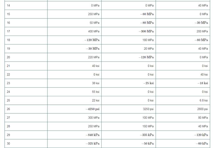
For the sets of given stresses on an element given in Table4−2, draw a complete Mohr’s circle, find the principal stresses and the maximum shear stress, and draw the principal stress element and the maximum shear stress element. Any stress components not shown are assumed to be zero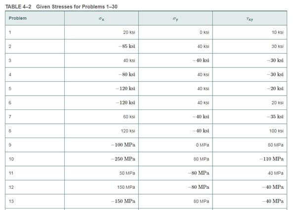
To draw: Mohr’s circle to determine the principal stresses and maximum shear stress. Also, draw the maximum shear stress element and principal stress element.
Answer to Problem 1P
A complete Mohr’s circle is given as below,
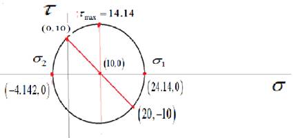
The maximum principal stress is
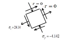
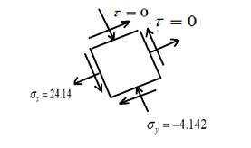
The principal stress element is given as,
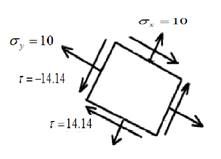
The maximum shear stress element is given as,

Explanation of Solution
Given Information:
Write the stresses in the x-direction, y-direction, and shear stress in the x-y plane.
Calculate the center of Mohr’s circle.
Calculate the radius of Mohr’s circle.
Draw the complete Mohr’s circle diagram.

Write the expression of principal stresses.
Substitute
Write the expression of maximum shear stress.
Substitute
Draw the principal stress elements.
Draw the maximum shear stress element.
Want to see more full solutions like this?
Chapter 4 Solutions
Machine Elements in Mechanical Design (6th Edition) (What's New in Trades & Technology)
Additional Engineering Textbook Solutions
Fluid Mechanics: Fundamentals and Applications
Heating Ventilating and Air Conditioning: Analysis and Design
Automotive Technology: Principles, Diagnosis, and Service (5th Edition)
Automotive Technology: Principles, Diagnosis, And Service (6th Edition) (halderman Automotive Series)
INTERNATIONAL EDITION---Engineering Mechanics: Statics, 14th edition (SI unit)
Engineering Mechanics: Statics & Dynamics (14th Edition)


- An element in plane stress on the fuselage of an airplane (figure part a) is subjected to compressive stresses with a magnitude of 42 MPa in the horizontal direction and tensile stresses with a magnitude of 9.5 MPa in the vertical direction (sec figure part b). Also, shear stresses with a magnitude of 15.5 MPa act in the directions shown. Determine the stresses acting on an element oriented at a clockwise angle of 40g from the horizontal. Show these stresses on a sketch of an element oriented at this angle.arrow_forwardAn clement m plane stress from the frame of a racing car is oriented at a known angle 8 (sec figure). On this inclined clement, the normal and shear stresses have the magnitudes and directions shown in the figure. Determine the normal and shear stresses acting on an clement whose sides are parallel to the \y axes, that is, determine crv, tr(_, and t, Show the results on a sketch of an clement oriented at B .arrow_forwardThe state of stress at a point in a machine component is given by ox = 120 MPa, oy = 55 MPa, Oz = -85 MPa, Oxy = -55 MPa, Oxz = -75 MPa, and oyz = 33 MPa. Construct the Mohr's circles of stress for this stress state and find the maximum shear stress.arrow_forward
- 1. Given a combination of stresses on an element shown in the figure, (a) draw a Mohr's circle representing the complete state of stress of the element, i.e. show prinicpal stresses (01,02), maximum shear stresses (Tmax), principal direction (0p), original orientation, and original stresses (Ox, Oy, Txy). (b) draw three-dimensional Mohr's circles showing the three principal stresses and absolute maximum shear stress. Oy = -50 MPa Txy 20 MPa Ox = -150 MPaarrow_forwardFor the stresses given with the cube below: 1. Compute the center, radius (R), principal normal stresses (0₁ and 03), max shear stress (Tmax) and draw the Mohr's Circle. 2. Compute the normal and shear stresses when the cube is rotated 20° clockwise from the horizontal plane and draw them on the cube. 3. The yield point stress (σyp) is 6 kPa. Determine if the material will fail under stresses shown using Tresca's Hexagon. вкра акра 6 экра 8 кра экра 4краarrow_forward160 MPa Find the approximate prime plane in degrees for the state of stress given in the figure. 45 MPa 100 MPa 100MPa 45 MPa 60 MPa O 66 O 55 O 44 O 33 O 2arrow_forward
- The state of stress at a point on an element of material is shown. Let sigmaX= 49.0 ksi, sigmaY= 17.0 ksi, and Txy= 11.0 ksi. Use this information to represent the principle state of stress and maximum in plane shear stress. Plot the mohr circle and state sigmaX' and sigmaY' and Tx'y' with unit. Also draw the state of stress on the rotated element.arrow_forwardThe state of plane stress at a point is represented on the element shown in the figure. The element oriented 40° 'counterclockwise. Find the value of ox 30 MPa 20 MPa -10 MPa +55.2 Mpa +11.4 Mpa -37.9 Mpa +24.7 Mpa -11.4 Mpa +37.9 Mpa -55.2 Mpa -24.7 Mpa +45.9 Mpa -45.9 Mpaarrow_forwardThe figure shows the stresses at a point. Determine the principal stresses and the maximum shear stress. Show these values on the faces of properly oriented stress blocks.arrow_forward
- The state of stress at a point in a member is shown in Figure Q1(a). Determine the stress components acting on the inclined plane AB by using the stress transformation equations.arrow_forwardThe point A in the following plot represents: A or T 0.5 -180 -90 90 180° -0.50, Graph of normal & shear stresses on inclined anglearrow_forwardFor the flat stress state shown in the figure. Use Mohr's circle to determine (show the procedure only with the use of geometry): a. Draw Mohr's circle indicating coordinates of the points that represent the given stress state, center, radius, coordinates of the points that represent the state the maximum and minimum normal stresses, coordinates of the maximum shear and angle of rotation from the stress given to the plane principal. b. Use the results of literal a to draw the element subjected to main forces and the element subjected to maximum shear. 12 MPa 19 MPа y 19 MPа 46 MPа 46 MPа 19 MPа 19 MPа 12 MPaarrow_forward
 Mechanics of Materials (MindTap Course List)Mechanical EngineeringISBN:9781337093347Author:Barry J. Goodno, James M. GerePublisher:Cengage Learning