
Concept explainers
Videos
Determine a numerical value for each nodal voltage in the circuit of Fig. 4.44.
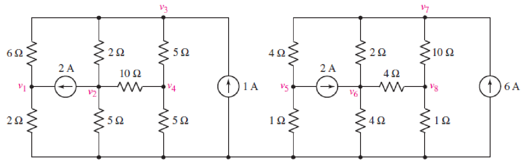
FIGURE 4.44
Find the numerical value of each nodal voltage.
Answer to Problem 14E
The nodal voltages are,
| S. No | Node | Nodal voltage |
| 1 | 3.078 V | |
| 2 | –2.349 V | |
| 3 | 0.3109 V | |
| 4 | –0.3454 V | |
|
5 | 1.02 V | |
|
6 | 9.217 V | |
| 7 | 13.095 V | |
| 8 | 2.6768 V |
Explanation of Solution
Calculation:
Refer to FIGURE 4.44 in the textbook.
Apply nodal analysis at node
Apply nodal analysis at node
Apply nodal analysis at node
Apply nodal analysis at node
Solve the equations by Cramer’s rule.
Find
Find
The value of
Find
The value of
Find
The value of
Find
The value of
Apply nodal analysis at node
Apply nodal analysis at node
Apply nodal analysis at node
Apply nodal analysis at node
Solve the equations by Cramer’s rule.
Find
Find
The value of
Find
The value of
Find
The value of
Find
The value of
Conclusion:
Thus, the nodal voltages are,
| S. No | Node | Nodal voltage |
| 1 | 3.078 V | |
| 2 | –2.349 V | |
| 3 | 0.3109 V | |
| 4 | –0.3454 V | |
|
5 | 1.02 V | |
|
6 | 9.217 V | |
| 7 | 13.095 V | |
| 8 | 2.6768 V |
Want to see more full solutions like this?
Chapter 4 Solutions
Loose Leaf for Engineering Circuit Analysis Format: Loose-leaf


- 47. For the circuit of Fig. 4.76, determine the value of resistor X if iz = 2.273 A. iz 30 19 7 V 7 Varrow_forwardCopyright ©2012 The McGraw-Hill Companies. Permission required for reproduction or display. All rights reserved. www.nitropdf.com Engineering Circuit Analysis 8th Edition Chapter Four Exercise Solutions 58. One possible solution: Replace the independent current source of Fig. 4.28 with a dependent current source. 20 10Ω 100 V 3Ω 50 (a) Make the controlling quantity 8v1, i.e. depends on a nodal voltage. (b) Make the controlling quantity 8i, i.e. depends on a mesh current. Copyright ©2012 The McGraw-Hill Companies. Permission required for reproduction or display. All rights reserved. www.nitropdf.com Engineering Circuit Analysis 8th Edition Chapter Four Exercise Solutions 59. Referring to the circuit of Fig. 4.34, our two nodal equations arearrow_forward1. Calculate the Vnu R, and find the Thevenin equivalent circuit of the circuits in Fig. 4.6. 4.7 ka 2.7 ko 15 ko 3AO 12 v 3.9 2.7 3.3 10 V 15 ko ko (a) (b) Figure 4.6 ww wwarrow_forward
- Obtain numerical values for the two mesh currents ij and iz in the circuit shown in Fig. 4.61. 32 5 V iz 12 V 14 2arrow_forwardUsing Thevenin's theorem, find the equivalent circuit to the left Fig. 4.30. Then find Practice: 9.1 the terminals in the circuit in 12 V 2A 40 10 VTh=6 V, RTh = 3 2, i = 1.5 A. Answer: %3D %3Darrow_forwardFind the Thevenin equivalent circuit of the circuit in Fig. 4.34 to the left of the terminals.arrow_forward
- Using Fig. 4.78, design a problem to help other students better understand superposition. Note, the letter k is a gain you can specify to make the problem easier to solve but must not be zeroarrow_forward(Example 4.8) Determine all node voltages and branch currents assuming = 100. Assume Active +5 V 100 ΚΩ www +10 V 2 ΚΩarrow_forwardQ5 Draw the output voltage waveform for each circuit in Fig. 4.30 with respect to the input. Show voltage levels. +I V +1 V 0- -I V +2 V Vutmery = 18 V -2 V (a) (b)arrow_forward
- 4.15 The limiter circuit of Fig. 4.5(a) is connected with V+ = 3 V and R = 100 2. The diode data sheet specifies a maximum reverse voltage of 10 V and maximum forward current of 50 mA. What are the maximum and minimum voltages that may be safely applied at vj? A Hide Answer -7 V≤v≤8V You might not be able to send or receive mail. To continue using Gmail, clean up space or get more storage. Figure 4.5 (a) + DI R www (a) EVarrow_forward47. For the circuit of Fig. 4.76, determine the value of resistor X if iz 2.273 A. 22 7 V 7 Varrow_forward4. Determine the value of the voltage labeled vi in Fig. 4.34. IA (()3 Aarrow_forward
 Introductory Circuit Analysis (13th Edition)Electrical EngineeringISBN:9780133923605Author:Robert L. BoylestadPublisher:PEARSON
 Delmar's Standard Textbook Of ElectricityElectrical EngineeringISBN:9781337900348Author:Stephen L. HermanPublisher:Cengage Learning
 Programmable Logic ControllersElectrical EngineeringISBN:9780073373843Author:Frank D. PetruzellaPublisher:McGraw-Hill Education
 Fundamentals of Electric CircuitsElectrical EngineeringISBN:9780078028229Author:Charles K Alexander, Matthew SadikuPublisher:McGraw-Hill Education
 Electric Circuits. (11th Edition)Electrical EngineeringISBN:9780134746968Author:James W. Nilsson, Susan RiedelPublisher:PEARSON
 Engineering ElectromagneticsElectrical EngineeringISBN:9780078028151Author:Hayt, William H. (william Hart), Jr, BUCK, John A.Publisher:Mcgraw-hill Education,