Vector Mechanics for Engineers: Statics and Dynamics
12th Edition
ISBN: 9781259638091
Author: Ferdinand P. Beer, E. Russell Johnston Jr., David Mazurek, Phillip J. Cornwell, Brian Self
Publisher: McGraw-Hill Education
bartleby

Videos

Textbook Question
Book Icon
Chapter 3.4, Problem 3.104P

Five separate force-couple systems act at the corners of a piece of sheet metal that has been bent into the shape shown. Determine which of these systems is equivalent to a force F = (10 lb)i and a couple of moment M = (15 lb·ft)j + (15 lb·ft)k located at the origin.

Chapter 3.4, Problem 3.104P, Five separate force-couple systems act at the corners of a piece of sheet metal that has been bent

Expert Solution & Answer
Check Mark
To determine

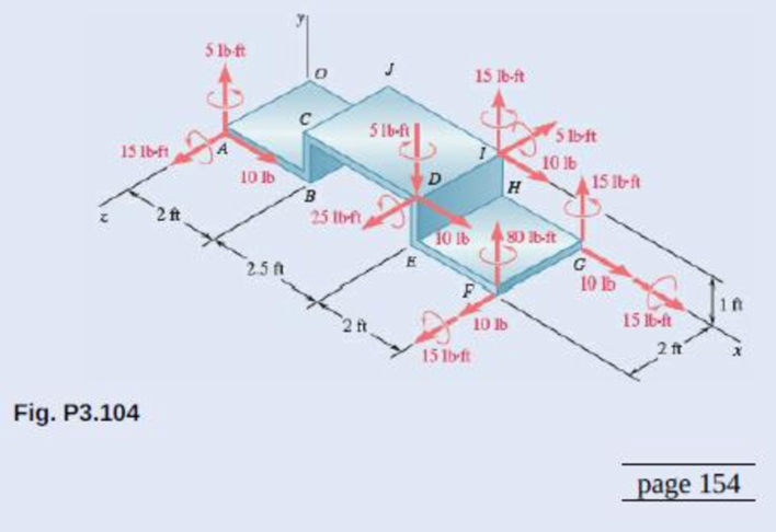
Identify the system having force equivalent F=(10lb)i and moment equivalent M=(15lbft)j+((15lbft))k at origin.

Answer to Problem 3.104P

System at corner D is the equivalent force-couple system.

Explanation of Solution

Take counterclockwise torques as positive quantities and clockwise torques as negative quantities.

Refer Figure P3.104.

There are five systems at corners A,D,I,F, and Among these, system at corner F cannot be equivalent. This is because that it does not have force in x-direction. All other systems have force F=(10lb)i. Now, to identify the equivalent system, move all other systems to origin O. This will noT change the forces.

Write the expression to calculate the force part of force couple system.

R=F

Here, R is the vector sum of all forces acting on the beam and F denotes any individual force.

Let check the couple part of force-couple system.

Write the expression to calculate the couple part of force couple system.

MR=(r×F)

Here, MR is the resultant moment and r is the length from axis of rotation to the point of application of force.

In the given system, at points A,D,G and I, moments in two directions are directly given. So the expression to find (r×F) is as follows.

(r×F)=M1+M2+(r×F)

Here, M1andM2 are the given couple moments

Rewrite the equation for MR by substituting the above expression for (r×F).

MR=M1+M2+(r×F) (I)

Write the determinant form to calculate r×F.

r×F=|ijkrirjrkFiFjFk| (II)

Here, ri is the component of r in x-direction, rj is the component of r in y-direction, rk is the is the component of r in z-direction, Fi is the component of F in x-direction, Fj is the component of F in y-direction, and Fk is the component of F in z-direction.

Conclusion:

Substitute (5lbft)j for M1, (15lbft)k for M2, (2ft)k for r  and (10lb)i for F in equation  (I) to find  moment resultant of system at corner A about point O (MA) .

MA=(5lbft)j+(15lbft)k+((2ft)k×(10lb)i) (III)

Solve (2ft)k×(10lb)i using equation (II).

(2ft)k×(10lb)i=|ijk002ft10lb00|=(0lbft)i(0lbft20lbft)j+(0lbf)k=(20lbft)j

Calculate MA by substituting (2ft)k×(10lb)i for (20lbft)j in equation (III).

MA=(5lbft)j+(15lbft)k+(20lbft)j=(25lbft)j+(15lbft)k

Substitute  (5lbft)j for M1, (25lbft)k for M2, [(4.5ft)i+(1ft)j+(2ft)k](2ft)k for r  and (10lb)i for F in equation  (I) to find moment resultant of system at corner D about point O (MD).

MD=(5lbft)j+(25lbft)k+[(4.5ft)i+(1ft)j+(2ft)k]×(10lb)i(IV)

Solve [(4.5ft)i+(1ft)j+(2ft)k]×(10lb)i using equation (II).

[(4.5ft)i+(1ft)j+(2ft)k]×(10lb)i=|ijk4.5ft1ft2ft10lb00|=(0lbf)i(0lbft20lbft)j+(0lbft10lbft)k=(20lbft)j(10lbft)k

Calculate MD by substituting (20lbft)j(10lbft)k(2ft)k×(10lb)i for [(4.5ft)i+(1ft)j+(2ft)k]×(10lb)i(20lbft)j in equation (IV).

MD=(5lbft)j+(25lbft)k+(20lbft)j(10lbft)k=(15lbft)j+(15lbft)k

Substitute  (15lbft)i for M1, (15lbft)j for M2, [(0ft)i+(0ft)j+(0ft)k] for r  and (10lb)i for F in equation  (I) to find moment resultant of system at corner G about point O (MG).

MG=(15lbft)i+(15lbft)j+[(0ft)i+(0ft)j+(0ft)k]×(10lb)i=(15lbft)i+(15lbft)j+(0ft)i+(0ft)j+(0ft)k=(15lbft)i+(15lbft)j

Substitute  (15lbft)j for M1, (5lbft)k for M2, [(4.5ft)i+(1ft)j] for r  and (10lb)j for F in equation  (I) to find moment resultant of system at corner I about point O (MI).

MD=(15lbft)j+(5lbft)k+([(4.5ft)i+(1ft)j]×(10lb)j)(V)

Solve [(4.5ft)i+(1ft)j]×(10lb)j using equation (III).

[(4.5ft)i+(1ft)j]×(10lb)j=|ijk(4.5ft)(1ft)(0ft)(10lb)00|=(0lbf)i(0lbft)j+(0lbft10lbft)k(10lbft)k

Calculate MD by substituting (10lbft)k for [(4.5ft)i+(1ft)j]×(10lb)j(20lbft)j in equation (V).

MI=(15lbft)j(5lbft)k+(10lbft)k=(15lbft)j(15lbft)k

From the above calculations, it is found that system at corner D has force equivalent F=(10lb)i and moment equivalent M=(15lbft)j+((15lbft))k at origin.

Therefore, System at corner D is the equivalent force-couple system.

Want to see more full solutions like this?

Subscribe now to access step-by-step solutions to millions of textbook problems written by subject matter experts!
Students have asked these similar questions
Reduce the given loading system to a force-couple system at point A. Then determine the distance x to the right of point A at which the resultant of the three forces acts. 380 lb 9" 15" HJ 12" 640 lb A Answers: Force-couple system at A. The force is positive if up, and the moment is positive if counterclockwise. R= M= i X= i Resultant 330 lb i lb lb-in. in.
A force P (200 + R)i + (250+ R)j + 300 k N, is acting at origin of the co-ordinate system, and a moment M = (10+ R)i + (100 - R)j + 30 k N-m, is acting at (0.5,1.0, -0.5) m from origin. Replace the given force system by equivalent wrench system, and determine the point where the axis of wrench will pass through x-z plane. (R = 41)
Replace the three forces shown by an equivalent force-couple system at point A. If the forces are replaced by a single resultant force, determine the distance d below point A to its line of action. 100 N 560 mm 560 mm 560 mm 260 N Answers: Force-couple system at A. The force is positive if to the right, and the couple is positive if counterclockwise. R= i N M = Single resultant force. d = i 120 N N•m mm

Chapter 3 Solutions

Vector Mechanics for Engineers: Statics and Dynamics

Ch. 3.1 - 3.11 and 3.12The tailgate of a car is supported by...Ch. 3.1 - 3.11 and 3.12The tailgate of a car is supported by...Ch. 3.1 - 3.13 and 3.14It is known that the connecting rod...Ch. 3.1 - 3.13 and 3.14It is known that the connecting rod...Ch. 3.1 - Form the vector product P1 P2 and use the result...Ch. 3.1 - The vectors P and Q are two adjacent sides of a...Ch. 3.1 - A plane contains the vectors A and B. Determine...Ch. 3.1 - A line passes through the points (4 m, 3 m) and (2...Ch. 3.1 - Prob. 3.19PCh. 3.1 - Determine the moment about the origin O of the...Ch. 3.1 - Before the trunk of a large tree is felled, cables...Ch. 3.1 - The 12-ft boom AB has a fixed end A. A steel cable...Ch. 3.1 - A 200-N force is applied as shown to the bracket...Ch. 3.1 - A force P of magnitude 200 N acts along the...Ch. 3.1 - A 6-ft-long fishing rod AB is securely anchored in...Ch. 3.1 - A precast concrete wall section is temporarily...Ch. 3.1 - In Prob. 3.22, determine the perpendicular...Ch. 3.1 - In Prob. 3.23, determine the perpendicular...Ch. 3.1 - In Prob. 3.24, determine the perpendicular...Ch. 3.1 - In Prob. 3.25, determine the perpendicular...Ch. 3.1 - In Prob. 3.25, determine the perpendicular...Ch. 3.1 - In Prob. 3.26, determine the perpendicular...Ch. 3.1 - In Prob. 3.26, determine the perpendicular...Ch. 3.1 - Determine the value of a that minimizes the...Ch. 3.2 - Given the vectors P = 2i + j + 2k, Q = 3i + 4j ...Ch. 3.2 - Form the scalar product B C and use the result...Ch. 3.2 - Three cables are attached to the top of the tower...Ch. 3.2 - Three cables are attached to the top of the tower...Ch. 3.2 - Knowing that the tension in cable AC is 280 lb,...Ch. 3.2 - Prob. 3.40PCh. 3.2 - Ropes AB and BC are two of the ropes used to...Ch. 3.2 - Prob. 3.42PCh. 3.2 - The 20-in. tube AB can slide along a horizontal...Ch. 3.2 - Solve Prob. 3.43 for the position corresponding to...Ch. 3.2 - Determine the volume of the parallelepiped of Fig....Ch. 3.2 - Given the vectors P = 3i + 2j + k, Q = 5i + j 2k,...Ch. 3.2 - A crane is oriented so that the end of the 25-m...Ch. 3.2 - 3.48The 25-m crane boom AO lies in the yz plane....Ch. 3.2 - To loosen a frozen valve, a force F with a...Ch. 3.2 - 3.50When a force F is applied to the handle of the...Ch. 3.2 - The 0.61 1.00-m lid ABCD of a storage bin is...Ch. 3.2 - 3.52The 0.61 1.00-m lid ABCD of a storage bin is...Ch. 3.2 - A farmer uses cables and winch pullers B and E to...Ch. 3.2 - Solve Prob. 3.53 when the tension in cable AB is...Ch. 3.2 - A force P of magnitude 520 lb acts on the frame...Ch. 3.2 - 3.56A force P acts on the frame shown at point E....Ch. 3.2 - The frame ACD is hinged at A and D and is...Ch. 3.2 - In Prob. 3.57, determine the moment about the...Ch. 3.2 - The triangular plate ABC is supported by...Ch. 3.2 - 3.60The triangular plate ABC is supported by...Ch. 3.2 - A regular tetrahedron has six edges of length a. A...Ch. 3.2 - Prob. 3.62PCh. 3.2 - Prob. 3.63PCh. 3.2 - In Prob. 3.55, determine the perpendicular...Ch. 3.2 - In Prob. 3.56, determine the perpendicular...Ch. 3.2 - In Prob. 3.57, determine the perpendicular...Ch. 3.2 - In Prob. 3.58, determine the perpendicular...Ch. 3.2 - In Prob. 3.59, determine the perpendicular...Ch. 3.2 - In Prob. 3.60, determine the perpendicular...Ch. 3.3 - Two 80-N forces are applied as shown to the...Ch. 3.3 - Two parallel 60-N forces are applied as shown to...Ch. 3.3 - A multiple-drilling machine is used to drill...Ch. 3.3 - Four pegs of the same diameter are attached to a...Ch. 3.3 - Prob. 3.74PCh. 3.3 - The shafts of an angle drive are acted upon by the...Ch. 3.3 - If P = 0 in the figure, replace the two remaining...Ch. 3.3 - 3.77If P = 20 lb in the figure, replace the three...Ch. 3.3 - The two couples shown are to be replaced with a...Ch. 3.3 - Solve part a of Prob. 3.78, assuming that two 15-N...Ch. 3.3 - Shafts A and B connect the gear box to the wheel...Ch. 3.3 - A 500-N force is applied to a bent plate as shown....Ch. 3.3 - Prob. 3.82PCh. 3.3 - Prob. 3.83PCh. 3.3 - A 30-lb vertical force P is applied at A to the...Ch. 3.3 - A worker tries to move a rock by applying a 360-N...Ch. 3.3 - A worker tries to move a rock by applying a 360-N...Ch. 3.3 - The shearing forces exerted on the cross section...Ch. 3.3 - Knowing that = 60, replace the force and couple...Ch. 3.3 - Three control rods attached to a lever ABC exert...Ch. 3.3 - A rectangular plate is acted upon by the force and...Ch. 3.3 - While tapping a hole, a machinist applies the...Ch. 3.3 - Prob. 3.92PCh. 3.3 - Replace the 250-kN force P with an equivalent...Ch. 3.3 - A 2.6-kip force is applied at point D of the...Ch. 3.3 - Prob. 3.95PCh. 3.3 - To keep a door closed, a wooden stick is wedged...Ch. 3.3 - A 46-lb force F and a 2120-lbin. couple M are...Ch. 3.3 - Prob. 3.98PCh. 3.3 - Prob. 3.99PCh. 3.3 - Prob. 3.100PCh. 3.4 - 3.101A 4-m-long beam is subjected to a variety of...Ch. 3.4 - A 4-m-long beam is loaded as shown. Determine the...Ch. 3.4 - Determine the single equivalent force and the...Ch. 3.4 - Five separate force-couple systems act at the...Ch. 3.4 - The weights of two children sitting at ends A and...Ch. 3.4 - Three stage lights are mounted on a pipe as shown....Ch. 3.4 - A beam supports three loads of given magnitude and...Ch. 3.4 - A 6 12-in. plate is subjected to four loads as...Ch. 3.4 - Gear C is rigidly attached to arm AB. If the...Ch. 3.4 - To test the strength of a 625 500-mm suitcase,...Ch. 3.4 - Prob. 3.111PCh. 3.4 - Prob. 3.112PCh. 3.4 - The roof of a building frame is subjected to the...Ch. 3.4 - Prob. 3.114PCh. 3.4 - A couple M and the three forces shown are applied...Ch. 3.4 - A machine component is subjected to the forces and...Ch. 3.4 - Prob. 3.117PCh. 3.4 - As follower AB rolls along the surface of member...Ch. 3.4 - A machine component is subjected to the forces...Ch. 3.4 - Two 150-mm-diameter pulleys are mounted on line...Ch. 3.4 - As an adjustable brace BC is used to bring a wall...Ch. 3.4 - In order to unscrew the tapped faucet A, a plumber...Ch. 3.4 - Prob. 3.123PCh. 3.4 - Four forces are applied to the machine component...Ch. 3.4 - A blade held in a brace is used to tighten a screw...Ch. 3.4 - A mechanic uses a crowfoot wrench to loosen a bolt...Ch. 3.4 - Four horizontal forces act on a vertical...Ch. 3.4 - Determine the magnitude of the force P for which...Ch. 3.4 - Prob. 3.129PCh. 3.4 - Prob. 3.130PCh. 3.4 - A concrete foundation mat of 5-m radius supports...Ch. 3.4 - Prob. 3.132PCh. 3.4 - Three forces of the same magnitude P act on a cube...Ch. 3.4 - A piece of sheet metal is bent into the shape...Ch. 3.4 - Prob. 3.135PCh. 3.4 - Prob. 3.136PCh. 3.4 - Two bolts at A and B are tightened by applying the...Ch. 3.4 - Two bolts at A and B are tightened by applying the...Ch. 3.4 - Prob. 3.139PCh. 3.4 - Prob. 3.140PCh. 3.4 - Prob. 3.141PCh. 3.4 - Prob. 3.142PCh. 3.4 - Replace the wrench shown with an equivalent system...Ch. 3.4 - Prob. 3.144PCh. 3.4 - Show that a wrench can be replaced with two...Ch. 3.4 - Show that a wrench can be replaced with two...Ch. 3 - A 300-N force P is applied at point A of the bell...Ch. 3 - A winch puller AB is used to straighten a fence...Ch. 3 - A small boat hangs from two davits, one of which...Ch. 3 - Prob. 3.150RPCh. 3 - A single force P acts at C in a direction...Ch. 3 - The 23-in. vertical rod CD is welded to the...Ch. 3 - In a manufacturing operation, three holes are...Ch. 3 - A 260-lb force is applied at A to the rolled-steel...Ch. 3 - The force and couple shown are to be replaced by...Ch. 3 - Prob. 3.156RPCh. 3 - Prob. 3.157RPCh. 3 - While using a pencil sharpener, a student applies...
Knowledge Booster
Background pattern image
Mechanical Engineering
Learn more about
Need a deep-dive on the concept behind this application? Look no further. Learn more about this topic, mechanical-engineering and related others by exploring similar questions and additional content below.
Similar questions
SEE MORE QUESTIONS
Recommended textbooks for you
Text book image
Elements Of Electromagnetics
Mechanical Engineering
ISBN:9780190698614
Author:Sadiku, Matthew N. O.
Publisher:Oxford University Press
Text book image
Mechanics of Materials (10th Edition)
Mechanical Engineering
ISBN:9780134319650
Author:Russell C. Hibbeler
Publisher:PEARSON
Text book image
Thermodynamics: An Engineering Approach
Mechanical Engineering
ISBN:9781259822674
Author:Yunus A. Cengel Dr., Michael A. Boles
Publisher:McGraw-Hill Education
Text book image
Control Systems Engineering
Mechanical Engineering
ISBN:9781118170519
Author:Norman S. Nise
Publisher:WILEY
Text book image
Mechanics of Materials (MindTap Course List)
Mechanical Engineering
ISBN:9781337093347
Author:Barry J. Goodno, James M. Gere
Publisher:Cengage Learning
Text book image
Engineering Mechanics: Statics
Mechanical Engineering
ISBN:9781118807330
Author:James L. Meriam, L. G. Kraige, J. N. Bolton
Publisher:WILEY
How to balance a see saw using moments example problem; Author: Engineer4Free;https://www.youtube.com/watch?v=d7tX37j-iHU;License: Standard Youtube License