
Concept explainers
Videos
For the transistor circuit shown in Fig. 3.125, find IB and VCE. Let β = 100, and VBE = 0.7 V.
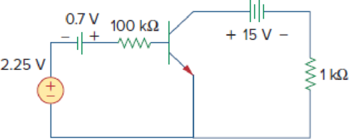
Figure 3.125
Find
Answer to Problem 89P
The value of
Explanation of Solution
Given data:
Refer Figure 3.125 in the textbook for the transistor circuit.
The common-emitter current gain
The base-emitter voltage
Formula used:
Write the expression for collector current in transistor.
Here,
Calculation:
Modify the given figure with the representation of currents and voltages as shown in Figure 1.
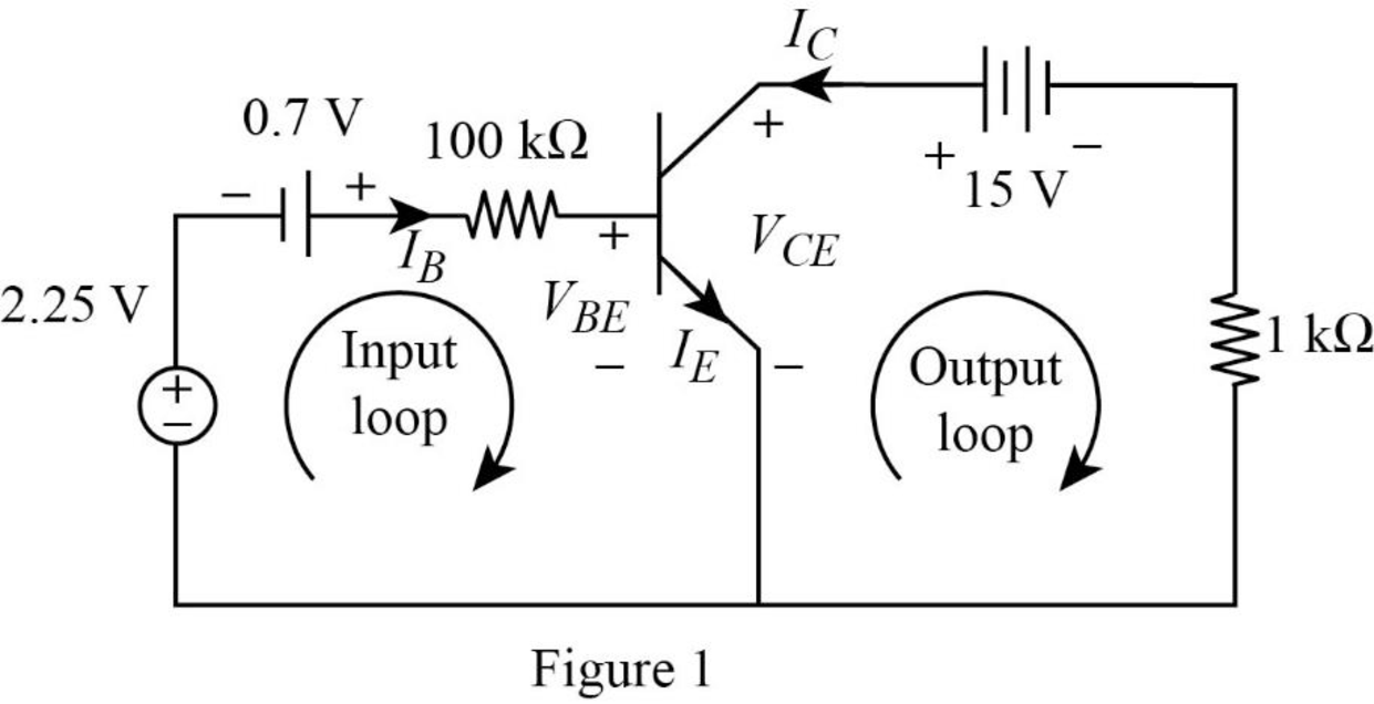
Apply Kirchhoff’s voltage law to input loop in Figure 1.
Substitute
Simplify the equation as follows.
Apply Kirchhoff’s voltage law to output loop in Figure 1.
Substitute equation (1) in (2).
Substitute
Conclusion:
Therefore, the value of
Want to see more full solutions like this?
Chapter 3 Solutions
Fundamentals of Electric Circuits


- Compute for Ie in the given circuit: Vcc. =+12V 3kn OV out 120kn 68kn Poc=140arrow_forwardFind Ig, Ic, and v, in the transistor circuit of Fig. 3.41. Assume that the transistor operates in the active mode and that B = 50. Ic 100 2 ww 20 k2 6 V Output loop + VBE 4 V Input loop Figure 3.41arrow_forwardFor the transistor in circuit shown below. 3 = 200. +6 V 10 ka Va 1 k2 If V, = 0 V, the value of I, and V, are (A) 6.43 mA, 2.4 V (B) 2.18 mA, 3.4 V (C) 0 A, 6 V (D) None of thesearrow_forward
- Q3: Fill in the following blanks: 1 The voltage gain for the circuit below is.. . Vee-12 V CC B-200 22kn Rg-11 l CEarrow_forward2. For the circuit of Fig. 3.54 (which is a model for the de operation of a bipolar junction transistor biased in forward active region), IB is measured to be 100 LA. Determine Ic and Ig. 1 kN R1 IB 150/g R2 1 k2 FIGURE 3.54arrow_forward1.Four 20-0 resistors are connected in parallel and the combination is connected to a 20-V emf device. The current in the device is =. Aarrow_forward
- Draw a circuit diagram to represent the DB101 chip, as shown in Fig. 3.8. Make sure that you label the input and output voltage in your drawing. Transformer Bridge Rectifier Input Output Vs Vo Top view Top view Fig. 3. 8 Diode full-wave rectifierarrow_forwardQ/ For the circuit shown below find I, VRI, and V.. 1K(ohm) D, R1 ITA D3 D4 Si Ge ideal 12v VT 2K(ohm) 3K(ohm) 2.5K(ohm)arrow_forwardIn the circuits of Fig. 3.2a and b, what aspects of Ohm’s law were validated?arrow_forward
- Refer to the given circuit below. Determine the Thevenin Equivalent EMF if R3 is to be analyzed.arrow_forwardD,on B2. 3.40. We wish to design a circuit that exhibits the input/output characteristic shown in Fig. 3.83. Using 1-k2 resistors, ideal diodes, and other components, construct the circuit. Vout + 2 V 0.5 -2 V + 2 V Vin -2 V 0.5 Figure 3.83arrow_forwardSuperposition V. Determine the current flowing through (Ix) and voltage across the 2 ohms resistor (Vx) a.) 3V acting alone a.1) Draw the circuit with 3v acting alone a.2) Solve to find Ix' and Vx' b.) 4A acting alone b.1) draw the circuit with 4A acting alone b.2) use circuit simulation software( NI Multisim, or Multisim live, or Everycircuit) simulate circuit (from b.1) and add properly ammeter and voltmeter to find Ix'' and Vx'' with 4A acting alone b.3.) Solve to find Ix'' and Vx'' (manually) c.) solve for Ix and Vx from results of (a.1, a.2, b.2) d.) simulate the original given circuit (with 3v and 4A) to check the results (from c, for Ix and Vx)arrow_forward
 Introductory Circuit Analysis (13th Edition)Electrical EngineeringISBN:9780133923605Author:Robert L. BoylestadPublisher:PEARSON
 Delmar's Standard Textbook Of ElectricityElectrical EngineeringISBN:9781337900348Author:Stephen L. HermanPublisher:Cengage Learning
 Programmable Logic ControllersElectrical EngineeringISBN:9780073373843Author:Frank D. PetruzellaPublisher:McGraw-Hill Education
 Fundamentals of Electric CircuitsElectrical EngineeringISBN:9780078028229Author:Charles K Alexander, Matthew SadikuPublisher:McGraw-Hill Education
 Electric Circuits. (11th Edition)Electrical EngineeringISBN:9780134746968Author:James W. Nilsson, Susan RiedelPublisher:PEARSON
 Engineering ElectromagneticsElectrical EngineeringISBN:9780078028151Author:Hayt, William H. (william Hart), Jr, BUCK, John A.Publisher:Mcgraw-hill Education,