
Mechanics of Materials (10th Edition)
10th Edition
ISBN: 9780134319650
Author: Russell C. Hibbeler
Publisher: PEARSON
expand_more
expand_more
format_list_bulleted
Concept explainers
Videos
Textbook Question
Chapter 2.2, Problem 2.2PP
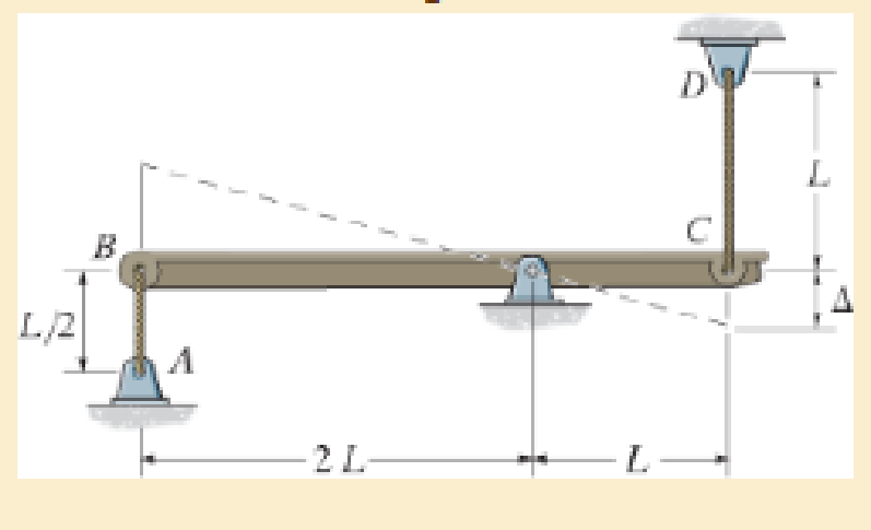
A loading causes the mamber to deform into the dashed shape. Explain how to determine the normal strains εCD and εAB·.The displacement Δ and the lettered dimensions are known.
P2–2
Expert Solution & Answer

Learn your wayIncludes step-by-step video

schedule05:32
Students have asked these similar questions
The strain components at a point in a body subjected to plane strain are &
850μ,
Ey
-300μ, and Yay
400μ. Determine the principal strains and the maximum
shearing strain at the point. Show the principal strain deformations and the maximum
shearing strain distortion on a sketch.
=
=
=
1. A loading causes the member to deform into the dashed shape. Explain how to
determine the normal strains ɛcd and ɛAB. The displacement A and the lettered
dimensions are known.
B
L.
L/2
A
2 L
(а)
L.
B
L/2
A
2 L
(b)
The strain components ɛ, Ey, and yy are given for a point in a body subjected to plane strain. Using Mohr's circle, determine the
principal strains, the maximum in-plane shear strain, and the absolute maximum shear strain at the point. Show the angle 0, the
principal strain deformations, and the maximum in-plane shear strain distortion in a sketch.
Ex = 300 µe, ɛ, = -710 pe, Vxy = -440 urad. Enter the angle such that -45°s0,s +45°.
Answer:
Ep1=
pe
Ep2=
με
Ymax in-plane =
prad
Yabsolute max.
prad
Əp =
Chapter 2 Solutions
Mechanics of Materials (10th Edition)
Ch. 2.2 - A loading causes the member to deform into the...Ch. 2.2 - A loading causes the mamber to deform into the...Ch. 2.2 - A loading causes the wires to elongate into the...Ch. 2.2 - A loading causes the block to deform into the...Ch. 2.2 - A loading causes the block to deform into the...Ch. 2.2 - When force P is applied to the rigid arm ABC,...Ch. 2.2 - If the force P causes the rigid arm ABC to rotate...Ch. 2.2 - The rectangular plate is deformed into the shape...Ch. 2.2 - The triangular plate is deformed into the shape...Ch. 2.2 - The square plate is deformed into the shape shown...
Ch. 2.2 - The square deforms into the position shown by the...Ch. 2.2 - The pin-connected rigid rods AB and BC are...Ch. 2.2 - The wire AB is unstretched when = 45. If a load...Ch. 2.2 - If a horizontal load applied to the bar AC causes...Ch. 2.2 - Determine the shear strain xy at corners A and B...Ch. 2.2 - Determine the shear strain xy at corners D and C...Ch. 2.2 - The material distorts into the dashed position...Ch. 2.2 - The material distorts into the dashed position...Ch. 2.2 - Part of a control linkage for an airplane consists...Ch. 2.2 - Part of a control linkage for an airplane consists...Ch. 2.2 - The nylon cord has an original length L and is...Ch. 2.2 - A thin wire, lying along the x axis, is strained...Ch. 2.2 - Determine the shear strain xy at corners A and B...Ch. 2.2 - Determine the shear strain xy at corners D and C...Ch. 2.2 - Determine the average normal strain that occurs...Ch. 2.2 - The corners of the square plate are given the...Ch. 2.2 - The triangular plate is fixed at its base, and its...Ch. 2.2 - The triangular plate is fixed at its base, and its...Ch. 2.2 - The triangular plate is fixed at its base, and its...Ch. 2.2 - The polysulfone block is glued at its top and...Ch. 2.2 - The corners of the square plate are given the...Ch. 2.2 - The corners of the square plate are given the...Ch. 2.2 - The block is deformed into the position shown by...Ch. 2.2 - The rectangular plate is deformed into the shape...Ch. 2.2 - The rectangular plate is deformed into the shape...Ch. 2.2 - The nonuniform loading causes a normal strain in...Ch. 2.2 - The rectangular plate undergoes a deformation...Ch. 2.2 - The fiber AB has a length L and orientation . If...Ch. 2.2 - If the normal strain is defined in reference to...
Additional Engineering Textbook Solutions
Find more solutions based on key concepts
The 60-mm-diameter steel shaft is subjected to the torques shown. Determine the angle of twist of end A with re...
Statics and Mechanics of Materials (5th Edition)
2.15 Compute the rectangular components parallel and perpendicular to the inclined planes shown.
Applied Statics and Strength of Materials (6th Edition)
Draw the free body diagram of each object. Prob. P5-1
INTERNATIONAL EDITION---Engineering Mechanics: Statics, 14th edition (SI unit)
If a force F = (60t2) N, where t is in seconds, is applied to the cable, determine the power developed by the f...
Engineering Mechanics: Dynamics (14th Edition)
The moment of force about point O.
Engineering Mechanics: Statics & Dynamics (14th Edition)
What parts are included in the vehicle chassis?
Automotive Technology: Principles, Diagnosis, and Service (5th Edition)
Knowledge Booster


Learn more about
Need a deep-dive on the concept behind this application? Look no further. Learn more about this topic, mechanical-engineering and related others by exploring similar questions and additional content below.Similar questions
- The strain components E, Ey, and yyare given for a point in a body subjected to plane strain. Using Mohr's circle, determine the principal strains, the maximum in-plane shear strain, and the absolute maximum shear strain at the point. Show the angle 0p, the principal strain deformations, and the maximum in-plane shear strain distortion in a sketch. Ex = 440 µE, ɛ, = -810 µE, Vxy = -540 µrad. Enter the angle such that -45°s0,s +45°. Answer: Ep1 = Ep2 = Ymax in-plane prad Yabsolute max. prad 0, =arrow_forwardDetermine the average normal strain along diagonal DB, based on the original plate (blue) and the deformed shaped (dashed line): 2 mm y C 300 mm 12 mm D -400 mm A 5 mm B 3 mm 4 mm 12 mm Xarrow_forwardThe strain components Ex, Ey, and Yxy are given for a point in a body subjected to plane strain. Using Mohr's circle, determine the principal strains, the maximum in-plane shear strain, and the absolute maximum shear strain at the point. Show the angle 0p, the principal strain deformations, and the maximum in-plane shear strain distortion in a sketch. Ex = 0 μE, Ey = 310 με, Yxy = 280 μrad. Enter the angle such that -45° ≤ 0,≤ +45° Answer: Ep1 = Ep2 = Ymax in-plane = Yabsolute max. = 0p = με με urad uradarrow_forward
- The strain components e x, e y, and γ xy are given for a point in a body subjected to plane strain. Using Mohr’s circle, determine the principal strains, the maximum in-plane shear strain, and the absolute maximum shear strain at the point. Show the angle θ p, the principal strain deformations, and the maximum in-plane shear strain distortion in a sketch. Ex Ey Yxy −1,570 με -430με -950 μradarrow_forwardFor the given state of plane strain, use Mohr's circle to determine the state of plane strain associated with axes x' and y rotated through the given angle 0. Ex = 0, Ɛy= +320µ, Yxy=-100µ, 0 = 25° (Round the final answers to one decimal place.) X The strains are Ex' = Ey'= Yx'y'=|arrow_forwardThe square plate is such that L = 273 mm. The corners of the square plate are given the displacements di = 7.027 mm and d2 = 4.014 mm. What is the shear strain along the edge of the plate at B? d2 L di di d2arrow_forward
- A stress element in a rock mass making up a slope experiences a 2D stress as follows: σx = 8 MPa, σy = 4 MPa , tauxy = 3 MPa A. By using the stress transformation equation, draw a curve of the stress variation experienced by the stress element at the axis of rotation angle θ = 0-180°. Use the interval θ = 1°, with the x-axis and stress as the y-axis. Mark on the curve where the principal stress and maximum shear stress occur. Draw the three stress curves completely and neatly B. Draw the stress element along with the magnitude and direction of the stress at the angle where the principal stress occurs and at the angle where the maximum shear stress occurs. C. Write down the direction vectors of the orientation of the principal stress (n1, and n₂) and the maximum shear stress (nmax). Write it in unit vector form i and j. D. Prove that the value of the stress invariant (I1, and I2) using the principal stress is reached and prove that the orthogonality condition of the direction cosine is…arrow_forwardThe piece of plastic is originally rectangular. Determine the average normal strain that occurs along the diagonals AC and DB. Determine the shear strain at corners A and B if the plastic distorts as shown by the dashed lines.arrow_forward(a) Determine the shear strain at corner A if the plate distorts as shown by the dashed line. (b) Determine the average normal strain that occurs along the diagonal AC and DB. 5 mm 2 mm 4 mm 2 mm IB 300 mm $2 mm D A 400 mm 3 mmarrow_forward
- The strain components ɛx, Ey, and yxy are given for a point in a body subjected to plane strain. Using Mohr's circle, determine the principal strains, the maximum in-plane shear strain, and the absolute maximum shear strain at the point. Show the angle 0p, the principal strain deformations, and the maximum in-plane shear strain distortion in a sketch. Ex = 0 HE, ɛy = 380 µɛ, Yxy = 230 µrad. Enter the angle such that -45° s 0,s+45°. Answer: Ep1 = με Ep2 = με Ymax in-plane = prad Yabsolute max. = prad 0, =arrow_forwardIn its undeformed state the assembly is represented by A-B-C-D, with theta = 0.53 in radians. The deformed shape is: A’-B’-C’-D. The deformation is such that the normal strain in AB is: ϵAB = 0.033 and that in CB is: ϵCB=0.031. Calculate the normal strain in BD (correctly up to four decimal places) neglecting the higher-order contributions due to the normal strains in AB and CB.arrow_forwardThe state of plane strain on an element is represented by the following components: Ex =D340 x 10-6, ɛ, = , yxy Ey =D110 x 10-6, 3D180 x10-6 ху Draw Mohr's circle to represent this state of strain. Use Mohrs circle to obtain the principal strains and principal plane.arrow_forward
arrow_back_ios
SEE MORE QUESTIONS
arrow_forward_ios
Recommended textbooks for you
 Elements Of ElectromagneticsMechanical EngineeringISBN:9780190698614Author:Sadiku, Matthew N. O.Publisher:Oxford University Press
 Mechanics of Materials (10th Edition)Mechanical EngineeringISBN:9780134319650Author:Russell C. HibbelerPublisher:PEARSON
 Thermodynamics: An Engineering ApproachMechanical EngineeringISBN:9781259822674Author:Yunus A. Cengel Dr., Michael A. BolesPublisher:McGraw-Hill Education
 Control Systems EngineeringMechanical EngineeringISBN:9781118170519Author:Norman S. NisePublisher:WILEY
 Mechanics of Materials (MindTap Course List)Mechanical EngineeringISBN:9781337093347Author:Barry J. Goodno, James M. GerePublisher:Cengage Learning
 Engineering Mechanics: StaticsMechanical EngineeringISBN:9781118807330Author:James L. Meriam, L. G. Kraige, J. N. BoltonPublisher:WILEY
Elements Of Electromagnetics
Mechanical Engineering
ISBN:9780190698614
Author:Sadiku, Matthew N. O.
Publisher:Oxford University Press
Mechanics of Materials (10th Edition)
Mechanical Engineering
ISBN:9780134319650
Author:Russell C. Hibbeler
Publisher:PEARSON
Thermodynamics: An Engineering Approach
Mechanical Engineering
ISBN:9781259822674
Author:Yunus A. Cengel Dr., Michael A. Boles
Publisher:McGraw-Hill Education
Control Systems Engineering
Mechanical Engineering
ISBN:9781118170519
Author:Norman S. Nise
Publisher:WILEY
Mechanics of Materials (MindTap Course List)
Mechanical Engineering
ISBN:9781337093347
Author:Barry J. Goodno, James M. Gere
Publisher:Cengage Learning
Engineering Mechanics: Statics
Mechanical Engineering
ISBN:9781118807330
Author:James L. Meriam, L. G. Kraige, J. N. Bolton
Publisher:WILEY
Mechanical Design (Machine Design) Clutches, Brakes and Flywheels Intro (S20 ME470 Class 15); Author: Professor Ted Diehl;https://www.youtube.com/watch?v=eMvbePrsT34;License: Standard Youtube License