
Videos
In an RLC circuit, these three elements are connected in series: a resistor of 20.0 Ω, a 35.0 mH inductor, and a 50.0 μF capacitor. The ac source of the circuit has an rms voltage of 100.0 V and an angular frequency of 1.0 × 10³ rad/s. (a) Find the rms current and the rms voltage across each of the circuit elements, (b) Does the current lead or lag the source voltage? (c) Draw a phasor diagram, (d) Find the average power dissipated.
(a)
The rms current and rms voltage across each of the circuit element.
Answer to Problem 93P
The rms current across each of the circuit element is
Explanation of Solution
Write the expression for capacitive reactance.
Here,
Write the expression for inductive reactance.
Here,
Write the expression for impedance.
Here,
Write the expression for rms current.
Write the expression for rms voltage across resistor.
Write the expression for rms voltage across inductor.
Write the expression for rms voltage across capacitor.
Conclusion:
Substitute,
Substitute,
Substitute,
Substitute,
Substitute,
Substitute,
Substitute,
Therefore, the average current through the coil during rotation is
(b)
Whether the current lead or lag voltage.
Answer to Problem 93P
Current lags voltage.
Explanation of Solution
The value of inductive reactance is
Conclusion:
Therefore, Current lags voltage.
(c)
Sketch the phasor diagram.
Answer to Problem 93P
The phasor diagram is shown below.
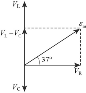
Explanation of Solution
Write the expression for phase angle.
Conclusion:
Substitute,
Therefore, the phasor diagram is.

(d)
The average power dissipated.
Answer to Problem 93P
The average power dissipated is
Explanation of Solution
Write the expression for power dissipated.
Conclusion:
Substitute,
Therefore, the average power dissipated is
Want to see more full solutions like this?
Chapter 21 Solutions
Physics
Additional Science Textbook Solutions
Physical Science
College Physics
Matter and Interactions
University Physics Volume 2
Conceptual Physics: The High School Physics Program


- In the AC circuit shown in Figure P32.3, R = 70.0 and the output voltage of the AC source is Vmax sin t. (a) If VR = 0.250 Vmax for the first time at t = 0.0100 s, what is the angular frequency of the source? (b) What is the next value of t for which VR = 0.250 Vmax? Figure P32.6 Problem 3 and 5.arrow_forwardFor an RLC series circuit, the voltage amplitude and frequency of the source are 100 V and 500 Hz, respectively; R=500 ; and L = 0.20H . Find the average power dissipated in the resistor for the following values for the capacitance: (a) C=2.0F and (b) C=2.0F .arrow_forwardThe emf of an ac source is given by v(t)=V0sint, where V0=100V and =200 . Find an expression that represents the output current of the source if it is connected across (a) a 20-pF capacitor, (b) a 20-mH inductor, and (c) a 50 resistor.arrow_forward
- An ac source of voltage amplitude 10 V delivers electric energy at a rate of 0.80 W when its current output is 2.5 A. What is the phase angle between the emf and the current?arrow_forwardIn a purely inductive AC circuit as shown in Figure P21.15, Vmax = 100. V. (a) The maximum current is 7.50 A at 50.0 Hz. Calculate the inductance L. (b) At what angular frequency is the maximum current 2.50A? Figure p21.15arrow_forwardA 40-mH inductor is connected to a 60-Hz AC source whose voltage amplitude is 50 V. If an AC voltmeter is placed across the inductor, what does it read?arrow_forward
- A 20-mH inductor is connected across an AC source with a variable frequency and a constant-voltage amplitude of 9.0 V. (a) Determine the reactance of the circuit and the maximum current through the inductor when the frequency Is set at 20 kHz. (b) Do the same calculations for a frequency of 60 Hz.arrow_forwardA series RLC circuit has resistance R = 50.0 and inductance L. = 0.500 H. (a) Find the circuits capacitance C if the voltage source operates at a frequency of f = 60.0 Hz and the impedance is Z = R = 50.0 . (b) What is the phase angle between the current and the voltage?arrow_forwardThe emf of an ac source is given by v(t)=v0sint. where V0=100V and at =200rad/s . Calculate the average power output of the source if it is connected across (a) a 20F capacitor, (b) a 20-mH inductor, and (c) a 50 resistor.arrow_forward
- An AC generator with an rms emf of 15.0 V is connected in series with a 0.54-H inductor. The frequency of the source emf is 70.0 Hz. Draw a phasor diagram for this circuit, including the current, the potential difference across the inductor, and the source emf. Draw your diagram with the current phasor pointing toward the right along the horizontal axis.arrow_forwardAn RLC series circuit consists of a 50 resistor, a 200F capacitor, and a 120-mN inductor whose coil has a resistance of 20. The source for the circuit has an tins emf of 240 V at a frequency of 60 Hz. Calculate the tins voltages across the (a) resistor, (b) capacitor, and (c) inductor.arrow_forward

 Physics for Scientists and Engineers: Foundations...PhysicsISBN:9781133939146Author:Katz, Debora M.Publisher:Cengage Learning
 Physics for Scientists and EngineersPhysicsISBN:9781337553278Author:Raymond A. Serway, John W. JewettPublisher:Cengage Learning
 Physics for Scientists and Engineers with Modern ...PhysicsISBN:9781337553292Author:Raymond A. Serway, John W. JewettPublisher:Cengage Learning
 College PhysicsPhysicsISBN:9781305952300Author:Raymond A. Serway, Chris VuillePublisher:Cengage Learning
 College PhysicsPhysicsISBN:9781285737027Author:Raymond A. Serway, Chris VuillePublisher:Cengage Learning