
Applied Statics and Strength of Materials (6th Edition)
6th Edition
ISBN: 9780133840544
Author: George F. Limbrunner, Craig D'Allaird, Leonard Spiegel
Publisher: PEARSON
expand_more
expand_more
format_list_bulleted
Concept explainers
Videos
Textbook Question
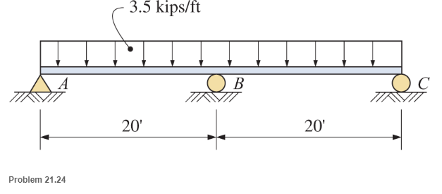
Chapter 21, Problem 21.24SP
For these problems, use any appropriate method of analysis. Unless noted otherwise, neglect the beam weight in all problems.
a. Find the reactions and draw complete shear and moment diagrams.
b. Assume mat the center support settles
Expert Solution & Answer
Want to see the full answer?
Check out a sample textbook solution
Students have asked these similar questions
Please answer Part 3, thank you
PART 1
Use the graphical method to construct the shear-force and bending-moment diagrams for the beam shown. Let a= 6 m, b = 3 m, PB = 70 kN, Pc= 100 kN, and PE= 30 kN. Construct the shear-force and bending-moment diagrams on paper and use the results to answer the questions in the subsequent parts of this GO exercise.
Calculate the reaction forces Ay and Dy acting on the beam. Positive values for the reactions are indicated by the directions of the red arrows shown on the free-body diagram below. (Note: Since Ax= 0, it has been omitted from the free-body diagram.)
Answer:
Ay = 50 kN
Dy= 150 kN
PART 2
Determine the shear force acting at each of the following locations:
(a) x = 3m
(b)x= 9 m
(c)x = 13.5 m
(d)x= 18 m
When entering your answers, use the shear force sign convention.
Answers:
(a) V= 50 kN
(b) V= -20 kN
(c) V= -120 kN
(d)V= 30 kN
PART 3 (PLEASE ANSWER, THANK YOU)
Determine the bending moment acting at each of the…
Figure 1 shows a 4 m length of a simply supported beam with a pinned support at A
and roller support at C. The beam carries a concentrated load of 16 kN at B.
Show the Free Body Diagram (FBD) of the beam then determine the reaction
force.
a.
Calculate the shear force, V. Draw Shear Force Diagram (SFD).
C.
Calculate the bending moment, M. Draw the Bending Moment Diagram (BMD).
b.
16 kN
A
-1 m→
- 3 m-
Figure 1
PART 1
Use the graphical method to construct the shear-force and bending-moment diagrams for the beam shown. Let a=3.5 m, b=2.0 m, PB = 2 kN, PC = 2 kN, and MB = 20 kN-m. Construct the shear-force and bending-moment diagrams on paper and use the results to answer the questions in the subsequent parts of this GO exercise.
IMAGE*
Calculate the reaction forces Ay and MA acting on the beam. Positive values for the reactions are indicated by the directions of the red arrows shown on the free-body diagram below. (Note: Since Ax = 0, it has been omitted from the free-body diagram.)
IMAGE*
PART 2
Determine the shear force acting at each of the following locations:(a) x = 0+ m (i.e., just to the right of fixed support A)(b) x = 3.5– m (i.e., just to the left of B)(c) x = 3.5+ m (i.e., just to the right of B)(d) x = 5.5– m (i.e., just to the left of C)When entering your answers, use the shear force sign convention.Answer:(a) V = ? kN.(b) V = ? kN.(c) V = ? kN.(d) V = ? kN.
PART 3…
Chapter 21 Solutions
Applied Statics and Strength of Materials (6th Edition)
Ch. 21 - Prob. 21.1PCh. 21 - Prob. 21.2PCh. 21 - Use the method of superposition to determine the...Ch. 21 - Draw complete shear and moment diagrams for the...Ch. 21 - Draw complete shear and moment diagrams for the...Ch. 21 - Draw complete shear and moment diagrams for the...Ch. 21 - Determine the reactions for the beam shown.Ch. 21 - Prob. 21.8PCh. 21 - 21.9 Select a southern pine timber beam () for the...Ch. 21 - For the continuous beams shown, find moments at...
Ch. 21 - For the continuous beams shown, find moments at...Ch. 21 - For the continuous beams shown, find moments at...Ch. 21 - Prob. 21.13SPCh. 21 - Prob. 21.14SPCh. 21 - Prob. 21.15SPCh. 21 - Prob. 21.16SPCh. 21 - Prob. 21.17SPCh. 21 - Prob. 21.18SPCh. 21 - Prob. 21.19SPCh. 21 - Prob. 21.20SPCh. 21 - For these problems, use any appropriate method of...Ch. 21 - For these problems, use any appropriate method of...Ch. 21 - Prob. 21.23SPCh. 21 - For these problems, use any appropriate method of...
Knowledge Booster


Learn more about
Need a deep-dive on the concept behind this application? Look no further. Learn more about this topic, mechanical-engineering and related others by exploring similar questions and additional content below.Similar questions
- Find the support reactions, draw the free-body diagram of the beams that shows the reactions and the equivalent loadings of the beams. Show the computation where M0 = 1,220 N-m, P = 2650 N, F = 3000 N, w0 = 1702 N/m, w1 = 1103 N/m, a = 3 m, b = 6 m, c = 2 marrow_forwardSolve for reactions (moments and forces) and draw bending moment diagram. MUST use method of least work.arrow_forwardload of 30kN/m. The second and fourth spans remain unloaded. Calculate the bending moments at B and C and draw the S.F. and B.M. diagrams.arrow_forward
- 1. For the beam shown below, calculate the support reactions. 200 lb Fixed support 38 Ib/ft 60° 6 ft 6 ft 6 ftarrow_forwardAnswer the following and show your solutions: Problem Calculate for the support reactions of the beam shown ( 10 kN 8 kN/m 8 kN 15 kN.m hinge 75 2.5 m 2 m 3 m 3m 3 m 4 marrow_forwardQUESTION 3 If the allowable bending stresses for a beam in one application is 6 kip/in2 in tension. The cross-section of the beam is W8 x 40. If the beam is 10 foot long and simply supported and has a concentrated load applied at x = 3 ft as shown below. • Generate the shear force and bending moment diagram in terms of P; • Based on the allowable maximum bending moment you just obtained above, calculate/ input the mazimm allowable value of the load P: please, pay attention to units, and calculate your answer to 1 decimal place.. 3 ft 7 ft kip.arrow_forward
- Figure 1 below shows a 5 m length of beam with a pinned support at A and roller support at E. The beam carries three concentrated loads of 10 kN, 5 kN and 15 kN at B, C and D, respectively. а. Show the Free Body Diagram (FBD) of the beam then determine the reaction force. b. Calculate the shear force, V. Draw Shear Force Diagram (SFD). Calculate the bending moment, M. Draw the Bending Moment Diagram (BMD). 10 kN 5 kN 15 kN A E B C D 1m 1m 1 m 2 m Figure 1 C.arrow_forwardThe beam is supported by a pin at point A and a roller at point C. A distributed load is applied to the beam. Neglect the weight and thickness of the beam. Hints: 1. will need to use similar triangles to find the height after sectioning at B. 2. Review direction of normal force, shear force and bending moment and which is positive or negative. W2 W1 A di d2 Values for the figure are given in the following table. Note the figure may not be to scale. Variable Value W1 190 N-m W2 440 N-m di 5 m d2 5 m a. Determine the magnitude of the normal force at point B, NB. . b. Determine the magnitude of the shear force at point B, VB- c. Is the shear force VB a positive or negative shear force? d. Determine the magnitude of the bending moment at point B, MB. e. Is the bending moment MB a positive or negative bending moment? Round your final answers to 3 significant digits/figures.arrow_forwardFind the support reactions, draw the free-body diagram of the beams that shows the reactions and the equivalent loadings of the beams. Show the computation where P = 950 lb, F = 2010 lb, w0 = 1090 lb/ft, a = 3 ft, b = 5.5 ft, c = 4 ftarrow_forward
- Part 1 Use the graphical method to construct the shear-force and bending-moment diagrams for the beam shown. Let a=11 ft, b=6 ft and w = 11 kips/ft. Calculate the reaction forces A, and Cy acting on the beam. Positive values for the reactions are indicated by the directions of the red arrows shown on the free-body diagram below. (Note: Since Ax = 0, it has been omitted from the free-body diagram.) Answers: Ay= kips, Cy= kips. Touthook dio b Carrow_forwardPart A Draw the moment diagram for the beam. Click on "add vertical line off" to add discontinuity lines. Then click on "add segment" button to add functions between the lines Draw the shear diagram for the beam. Click on "add vertical line off" to add discontinuity lines. Then click on "add segment" button to add functions between the line + 10 kN 10 kN 15 kN-m 10 kN 10 kN B 15 kN-m No elements selected -2 m 2 m-- -2 m- M (kN m) No elements selected +2 m- 2 m 20 18+ 16+ + V (kN) 14 12+ 10 20 T 18+ 8- 6- 4+ 2- 0- 16 + 14 12+ + 10 8 I (m) 6+ 4+ -20 -4+ -6- 2 -8 -10+ -12+ + + * (m) -20 -4+ -6+ 8 2. 4. -14 -16+ -18+ -20 -10 -12 -14 -16+ + Add discontinuity lines and select segments to add to the canvas. -18 -20 I Add discontinuity lines and select segments to add to the canvas.arrow_forwardAnalyze the given beam using consistent deformation method (force method), show complete solution. Draw the shear and moment diagram of the beam, USE the Force at SUPPORT C as the redundant force for the analysis.arrow_forward
arrow_back_ios
SEE MORE QUESTIONS
arrow_forward_ios
Recommended textbooks for you
 Elements Of ElectromagneticsMechanical EngineeringISBN:9780190698614Author:Sadiku, Matthew N. O.Publisher:Oxford University Press
 Mechanics of Materials (10th Edition)Mechanical EngineeringISBN:9780134319650Author:Russell C. HibbelerPublisher:PEARSON
 Thermodynamics: An Engineering ApproachMechanical EngineeringISBN:9781259822674Author:Yunus A. Cengel Dr., Michael A. BolesPublisher:McGraw-Hill Education
 Control Systems EngineeringMechanical EngineeringISBN:9781118170519Author:Norman S. NisePublisher:WILEY
 Mechanics of Materials (MindTap Course List)Mechanical EngineeringISBN:9781337093347Author:Barry J. Goodno, James M. GerePublisher:Cengage Learning
 Engineering Mechanics: StaticsMechanical EngineeringISBN:9781118807330Author:James L. Meriam, L. G. Kraige, J. N. BoltonPublisher:WILEY
Elements Of Electromagnetics
Mechanical Engineering
ISBN:9780190698614
Author:Sadiku, Matthew N. O.
Publisher:Oxford University Press
Mechanics of Materials (10th Edition)
Mechanical Engineering
ISBN:9780134319650
Author:Russell C. Hibbeler
Publisher:PEARSON
Thermodynamics: An Engineering Approach
Mechanical Engineering
ISBN:9781259822674
Author:Yunus A. Cengel Dr., Michael A. Boles
Publisher:McGraw-Hill Education
Control Systems Engineering
Mechanical Engineering
ISBN:9781118170519
Author:Norman S. Nise
Publisher:WILEY
Mechanics of Materials (MindTap Course List)
Mechanical Engineering
ISBN:9781337093347
Author:Barry J. Goodno, James M. Gere
Publisher:Cengage Learning
Engineering Mechanics: Statics
Mechanical Engineering
ISBN:9781118807330
Author:James L. Meriam, L. G. Kraige, J. N. Bolton
Publisher:WILEY
Types Of loads - Engineering Mechanics | Abhishek Explained; Author: Prime Course;https://www.youtube.com/watch?v=4JVoL9wb5yM;License: Standard YouTube License, CC-BY