
Concept explainers
Videos
For each of the circuits in Fig. 2.40, find the current I and compute the power absorbed by the resistor.
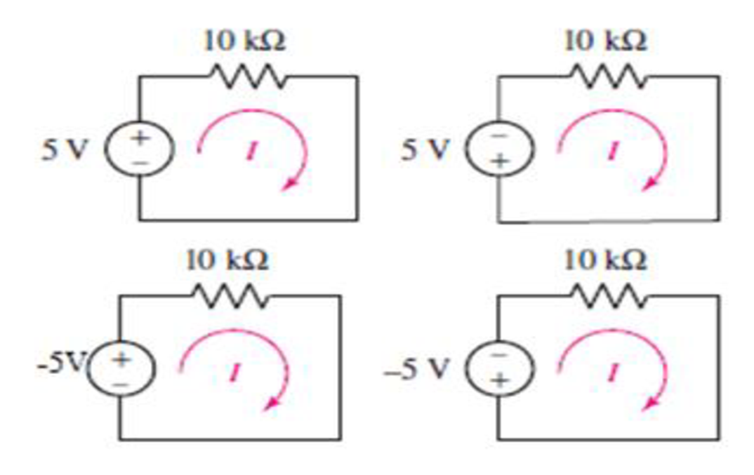
FIGURE 2.40
Find the current and power absorbed by resistor for each circuit in the given Figures.
Answer to Problem 54E
The current flowing in the circuit in Figure 1 is
The power absorbed by the resistor in Figure 1 is
The current flowing in the circuit in Figure 2 is
The power absorbed by the resistor in Figure 2 is
The current flowing in the circuit in Figure 3 is
The power absorbed by the resistor in Figure 3 is
The current flowing in the circuit in Figure 4 is
The power absorbed by the resistor in Figure 4 is
Explanation of Solution
Formula used:
The expression for current is as follows.
Here,
The expression for power absorbed by the resistor is as follows.
Here,
Calculation:
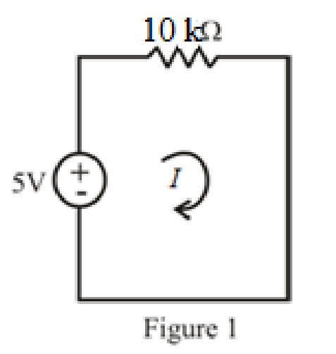
Refer to FIGURE 2.40(a) in the textbook.
The circuit diagram is redrawn as shown in Figure 1.
Substitute
Substitute
Refer to FIGURE 2.40(b) in the textbook.
The circuit diagram is redrawn as shown in Figure 2.
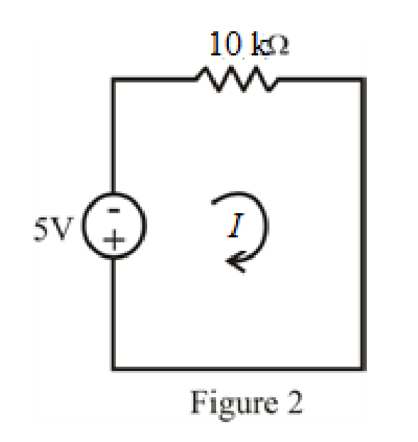
Refer to redrawn Figure 2
Substitute
Substitute
Refer to FIGURE 2.40(c) in the textbook.
The circuit diagram is redrawn as shown in Figure 3.
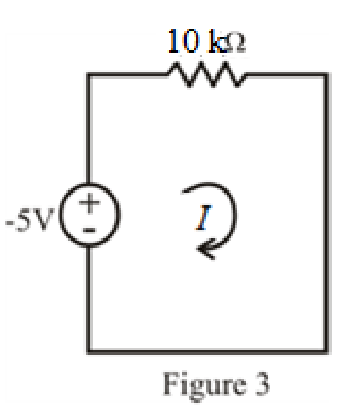
Refer to redrawn Figure 3.
Substitute
Substitute
Refer to FIGURE 2.40(d) in the textbook.
The circuit diagram is redrawn as shown in Figure 4.
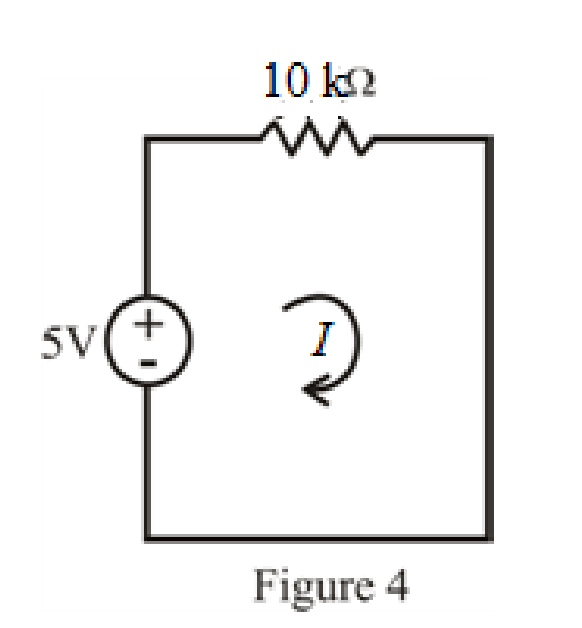
Refer to redrawn Figure 4.
Substitute
Substitute
Conclusion:
Thus, The current flowing in the circuit in Figure 1 is
The power absorbed by the resistor in Figure 1 is
The current flowing in the circuit in Figure 2 is
The power absorbed by the resistor in Figure 2 is
The current flowing in the circuit in Figure 3 is
The power absorbed by the resistor in Figure 3 is
The current flowing in the circuit in Figure 4 is
The power absorbed by the resistor in Figure 4 is
Want to see more full solutions like this?
Chapter 2 Solutions
Loose Leaf for Engineering Circuit Analysis Format: Loose-leaf


- 2.19 plz solve it with step by step and explain itarrow_forward7. In Fig. 2.41, the potential of point A is –30 V. Using Kirchhoff's voltage law, find (a) value of V and (b) power dissipated by 5 Q resistance. All resistances are in ohms. [100 V; 500 W| + 20 V- ww- 10 V 11A 18 30 V 12 ww 60 V -30 v 12 8A 4 15 Fig. 2.41 Fig. 2.42 Fig. 2.43 ww ww wwarrow_forward2. The internal resistance of the battery is 0.3 2. Find I, I1 and voltmeter readings V₁ and V₂ for the circuit shown in Figure 2. Ans.: I = 1.35 A, I₁ = 0.34 A, V₁ = 3.7 V, and V2 = 16.9 V. 7.115 20 V, 0.392 I 20 W 822 w ¾602 Figure 2. 792 w 1022 W 11 www 122arrow_forward
- 2.9. You quickly need a 150 2 resistor but have a store of only 100 N resistors. What can you do?arrow_forward2. In the circuit shown there are five resistors. The battery is not an ideal battery and has an internal resistance of 25 0. A) What is the power dissipated by the 300 resistor below? B) What is the energy lost in the battery in 10 minutes of operation? C) If the 300 resistor burns out is the energy lost in the battery the same? Why or why not? 200 50V 502 m 300. 100 m 600arrow_forward*30. Sketch v, for the network of Fig. 2.174 and determine the de voltage available. Vi 100 V Ideal diodes -100 V 2.2 k2 2.2 k2 2.2 k2arrow_forward
- 8. By applying nodal analysis to the circuit of Fig. 2.90, find lab Ibd and Ibe All resistance values are in 22 10 8 Uab = 2A, Ibd = 1 A, 1bc = A] 21 21 [Hint. It would be helpful to convert resistance into conductances.] ohms. 6A a 0.5 b www 0.25 d 0.5 ww 0.5 0.25 4Aarrow_forwardProblem 2.33. Readings of the ammeter and voltmeter are shown in the following figure. A. Based on voltage and current measurements determine if the element is a resistance or a current source. B. Find the power delivered to the circuit element or taken from it in every case. A+ A) +2 mA +V- -5 V B) +A- -0.5 A -V+ -10 V A +1 μA -V+ -10 Varrow_forward2. 5. 1. The maximum measurable voltage on Range B is Page 2: 100 micro A, 1 k ohms Page 3: Range A R3 R2 R1 3. 300k ohms 100 k ohms 99 k ohms Range B Page 4: Range C Page 5: O 20.0 V O 10.1 V age 6: O 30.1 V O 10.0 V ge 7: Previous Page Next Page Page 11 of 70 ge 8: Submit Quiz 56 of 70 questions saved F 10 F 11 F 12arrow_forward
- 7. In Fig. 2.41, the potential of point A is -30 V. Using Kirchhoff's voltage law, find (a) value of V and (b) power dissipated by 5 2 resistance. All resistances are in ohms. [100 V; 500 W] + 20 V- 10 ww A 14 11A Ž18 12 30 VI 12 ww 多2 60 V -30 Va 8A 4 ww Fig. 2.41 Fig. 2.42 Fig. 2.43 8. Using KVL and KCL, find the values of V and I in Fig. 2.42. All resistances are in ohms. [80 V; -4 A] 9. Using KCL, find the values V, I, 1, and I, in the circuit of Fig. 2.43. All resistances are in ohms. [VA = 12 V ; I, = 2/3 A; I, = 1 A; I,= 4/3 A] 10. A bridge network ABCD is arranged as follows : Resistances between terminals A-B, B-C, C-Đ, D-A, and B-Đ are 10, 20, 15, 5 and 40 ohms respec- tively. A 20 V battery of negligible internal resistance is connected between terminals A and C. Determine the current in each resistor. JAB = 0.645 A; BC = 0.678 A; AD = 1.025 A; DB = 0.033 A; DC= 0.992 A] 11. Two batteries A and B are connected in parallel and a load of 10 Qis connected across their…arrow_forward2.5 From the circuit in the figure, find the current i and the power supplied by the 20 mà source. Ozoma mA 34 kn 1 krarrow_forward(vi) The Tesla Model 3 battery pack has 75 kWh of storage and features 46 parallel strings of 96 cells each. What is the energy stored in each cell? (ix) A home charger for the Tesla Model 3 with the 75 kWh battery is fed by a single-phase 230 V, 6 kw supply, and the efficiency of the charger nog is 88 %. What is the line current from the supply? How long does it take to charge a fully discharged battery pack to 100 %. (x) The 75 kWh Tesla Model 3 can be recharged to 80 % in 30 minutes using a three-phase 400 V supply. The efficiency of the charger nehg is 88 %. What are the power and current ratings of the charger?arrow_forward
 Introductory Circuit Analysis (13th Edition)Electrical EngineeringISBN:9780133923605Author:Robert L. BoylestadPublisher:PEARSON
 Delmar's Standard Textbook Of ElectricityElectrical EngineeringISBN:9781337900348Author:Stephen L. HermanPublisher:Cengage Learning
 Programmable Logic ControllersElectrical EngineeringISBN:9780073373843Author:Frank D. PetruzellaPublisher:McGraw-Hill Education
 Fundamentals of Electric CircuitsElectrical EngineeringISBN:9780078028229Author:Charles K Alexander, Matthew SadikuPublisher:McGraw-Hill Education
 Electric Circuits. (11th Edition)Electrical EngineeringISBN:9780134746968Author:James W. Nilsson, Susan RiedelPublisher:PEARSON
 Engineering ElectromagneticsElectrical EngineeringISBN:9780078028151Author:Hayt, William H. (william Hart), Jr, BUCK, John A.Publisher:Mcgraw-hill Education,