
Electronics Fundamentals: Circuits, Devices & Applications
8th Edition
ISBN: 9780135072950
Author: Thomas L. Floyd, David Buchla
Publisher: Prentice Hall
expand_more
expand_more
format_list_bulleted
Concept explainers
Videos
Textbook Question
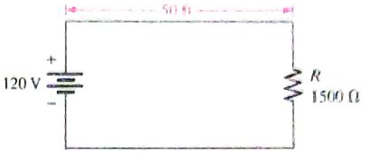
Chapter 2, Problem 37P
A 120 V source is to be connected to a
Expert Solution & Answer
Want to see the full answer?
Check out a sample textbook solution
Students have asked these similar questions
R1 of 90 kilo ohm and R2 of 10 kilo ohm are in series across a 43-volt source. A) Draw the schematic diagram. B) What is the voltage drop at R2?
Determine the voltage across R1 in the figure below, if the source is 10 volts, the Zener is 6.8 volts, R1= 1k ohms and R2= 20k ohms.
The figure is shown a circuit consisting of a resistor Rị in series with two resistors
R2 and R3 in parallel. The circuit is connected across a constant 100 V supply.
When switch S is open, the ammeter A, reads 8 amperes. When switch S is closed
A1 reads 10 amperes and A2 reads 4 A. determine (a) ohms of
resistors R1, R2 and R3. (b) Voltage across R,& R2 when S is open. (c) Voltage
across R1 & R2 when S is closed.
R1
{A1 -v
A2
S1
100V
R2
R3
Chapter 2 Solutions
Electronics Fundamentals: Circuits, Devices & Applications
Ch. 2 - The number of neutrons in the nucleus is the...Ch. 2 - The unit of charge is the ampere.Ch. 2 - Energy in a battery is stored in the form of...Ch. 2 - Prob. 4TFQCh. 2 - In a five-band precision resistor, the fourth band...Ch. 2 - A rheostat performs the same function as a...Ch. 2 - A strain gauge changes resistance in response to...Ch. 2 - Prob. 8TFQCh. 2 - Prob. 9TFQCh. 2 - The three basic measurements that can be done by a...
Ch. 2 - A neutral atom with an atomic number of three has...Ch. 2 - Electron orbits are called shells nuclei waves...Ch. 2 - Materials in which current cannot be established...Ch. 2 - When placed close together, a positively charged...Ch. 2 - The charge on a single electron is 6.2510-18C...Ch. 2 - Prob. 6STCh. 2 - Prob. 7STCh. 2 - Prob. 8STCh. 2 - Prob. 9STCh. 2 - Prob. 10STCh. 2 - Prob. 11STCh. 2 - There is no current in a circuit when a series...Ch. 2 - Prob. 13STCh. 2 - Potentiometers and rheostats are types of voltage...Ch. 2 - The current in a given circuit is not to exceed 22...Ch. 2 - How many coulombs of charge do 501031 electrons...Ch. 2 - How many electrons does it take to make 80C of...Ch. 2 - What is the charge in coulombs of the nucleus of a...Ch. 2 - What is the charge in coulombs of the nucleus of a...Ch. 2 - Detemine the voltage in each of the following...Ch. 2 - Five hundred joules of energy are used to move 100...Ch. 2 - What is the voltage of a battery that uses 800 J...Ch. 2 - How much energy does a 12 V battery in your car...Ch. 2 - Assume that a solar battery charger delivers 2.5 J...Ch. 2 - If the solar cell in Problem 9 has moved the...Ch. 2 - Determine the current in each of the following...Ch. 2 - Six-tenths coulomb passes a point in 3 s. What is...Ch. 2 - How long does it take 10 C to flow past a point if...Ch. 2 - How many coulombs pass a point in 0.1 s when the...Ch. 2 - Figure 2-61(a) shows color-coded resistors....Ch. 2 - 16. Find the minimum and the maximum resistance...Ch. 2 - If you need a 270 resistor with 5% tolerance. what...Ch. 2 - Determine the resistance value and tolerance for...Ch. 2 - Determine the resitance and tolerance of each of...Ch. 2 - Determine the color bands for each of the...Ch. 2 - Determine the resistance and tolerance of each of...Ch. 2 - Determine the color bands for each of the...Ch. 2 - Determine the resistance values represented by the...Ch. 2 - The adjustable contact of a linear potentlometer...Ch. 2 - Trace the current path in the lamp circuit of...Ch. 2 - With the switch in either position, redraw the...Ch. 2 - Show the placement of an ammeter and a voltmeter...Ch. 2 - Show how you would measure the resistance of R2 in...Ch. 2 - In Figure 2-64 what does each voltmeter indicate...Ch. 2 - In Figure 2-64, show how to connect an ammeter to...Ch. 2 - What is the voltage reading of the meter in Figure...Ch. 2 - How much resistance is the meter in Figure 2-66...Ch. 2 - Determine the resistance indicated by each of the...Ch. 2 - A multimeter has the following ranges:...Ch. 2 - A resistor with a current of 2 A through it in an...Ch. 2 - If 5741015 electrons flow through a speaker wire...Ch. 2 - A 120 V source is to be connected to a 1500...Ch. 2 - Determine the resistance and tolerance of each...Ch. 2 - Prob. 39PCh. 2 - Through which resistor in Figure 2-70 is there...Ch. 2 - In Figure 2-70, show the proper placement of...Ch. 2 - Show the proper placement of voltmeters to measure...Ch. 2 - Devise a switch arrangement where by two voltage...
Knowledge Booster


Learn more about
Need a deep-dive on the concept behind this application? Look no further. Learn more about this topic, electrical-engineering and related others by exploring similar questions and additional content below.Similar questions
- Source room Sink room switch A batteries resistors B D -W- -W -W W wires wiresarrow_forwardQ1:- Find the value of the electric current passing in (6Ω) in figure (2-24) by using current divider rule B. 6Ω 24 ΩΣ 24 Ωarrow_forwardWhat is the greatest voltage that can be applied across a -W, 2.7-MQ resistor without causing it to overheat?arrow_forward
- Two resistors : R1= 8 ohm. and R2=0.03 kohm. The voltage across R1= 5 V. what is the value of current across the R2? O 1.6A 0.1666A 0.625A 0.131Aarrow_forwardGiven four 1ohms resistor. State how they must be connected to give an overall resistance of 1.4ohm 1ohms 1whole number1.3ohms 2whole number 1.2ohms, all four resistor being connected in each case.arrow_forwardA 6 – ohm resistor is connected in series to a parallel connection of a 30 – ohm resistor and a variable resistor R. What must be the value of R such that the power taken by the 6-ohm resistor will be equal to the power taken by R?arrow_forward
- Resistor R2 has a resistance of 220 ohm and a voltage drop of 44 v. What is the current flow through resistor R3arrow_forwardA piece of wire has a resistance of 100 ohms. It is cut into 10 equal pieces. These shorter pieces are then connected in parallel. Determine the new resistance.arrow_forwardIn the figure R₁-3.41R, the ammeter resistance is zero, and the battery is ideal. What multiple of e/R gives the current in the ammeter? EH Number Units *E/Rarrow_forward
arrow_back_ios
SEE MORE QUESTIONS
arrow_forward_ios
Recommended textbooks for you
 Introductory Circuit Analysis (13th Edition)Electrical EngineeringISBN:9780133923605Author:Robert L. BoylestadPublisher:PEARSON
 Delmar's Standard Textbook Of ElectricityElectrical EngineeringISBN:9781337900348Author:Stephen L. HermanPublisher:Cengage Learning
 Programmable Logic ControllersElectrical EngineeringISBN:9780073373843Author:Frank D. PetruzellaPublisher:McGraw-Hill Education
 Fundamentals of Electric CircuitsElectrical EngineeringISBN:9780078028229Author:Charles K Alexander, Matthew SadikuPublisher:McGraw-Hill Education
 Electric Circuits. (11th Edition)Electrical EngineeringISBN:9780134746968Author:James W. Nilsson, Susan RiedelPublisher:PEARSON
 Engineering ElectromagneticsElectrical EngineeringISBN:9780078028151Author:Hayt, William H. (william Hart), Jr, BUCK, John A.Publisher:Mcgraw-hill Education,
Introductory Circuit Analysis (13th Edition)
Electrical Engineering
ISBN:9780133923605
Author:Robert L. Boylestad
Publisher:PEARSON
Delmar's Standard Textbook Of Electricity
Electrical Engineering
ISBN:9781337900348
Author:Stephen L. Herman
Publisher:Cengage Learning
Programmable Logic Controllers
Electrical Engineering
ISBN:9780073373843
Author:Frank D. Petruzella
Publisher:McGraw-Hill Education
Fundamentals of Electric Circuits
Electrical Engineering
ISBN:9780078028229
Author:Charles K Alexander, Matthew Sadiku
Publisher:McGraw-Hill Education
Electric Circuits. (11th Edition)
Electrical Engineering
ISBN:9780134746968
Author:James W. Nilsson, Susan Riedel
Publisher:PEARSON
Engineering Electromagnetics
Electrical Engineering
ISBN:9780078028151
Author:Hayt, William H. (william Hart), Jr, BUCK, John A.
Publisher:Mcgraw-hill Education,
NMOS vs PMOS and Enhancement vs Depletion Mode MOSFETs | Intermediate Electronics; Author: CircuitBread;https://www.youtube.com/watch?v=kY-ka0PriaE;License: Standard Youtube License