
Videos
(a)
To plot:
A graph of
Answer to Problem 2.70HP
The plot of
Explanation of Solution
Calculation:
The formula to calculate the resistance
Substitute
Substitute
Substitute
Substitute
Substitute
Substitute
Substitute
Substitute
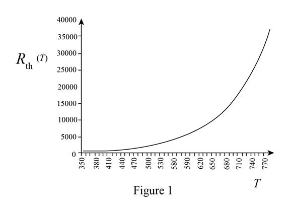
The plot of
The required diagram is shown in Figure 1
(b)
The expression for the equivalent resistance.
To plot:
A sketch of resistance
Answer to Problem 2.70HP
The expression for the equivalent resistance is
Explanation of Solution
Calculation:
The expression for the equivalent resistance is given by,
Substitute
Substitute
Substitute
Substitute
Substitute
Substitute
Substitute
Substitute
Substitute
Substitute
Substitute
Substitute
Substitute
Substitute
Substitute
Substitute
Substitute
Substitute
The plot for the equivalent resistance for different temperature ranges is shown in Figure 2
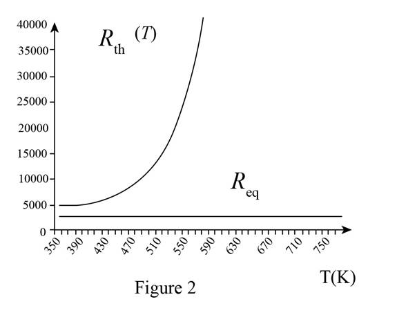
Conclusion:
Therefore, the expression for the equivalent resistance is
Want to see more full solutions like this?
Chapter 2 Solutions
Principles and Applications of Electrical Engineering


- For residential water heaters, the Consumer Product Safety Commission suggests a maximum temperature setting of ___________ F (_____________ C). Some states have laws stating a maximum temperature setting of ____________ F (________________ C).arrow_forwardFill in all the missing values. Refer to the formulas that follow. Resistance Capacitance Time constant Total time 150 k 100 F 350 k 35 s 350 pF 10 s 0.05 F 1.2 M 0.47 F 12F 0.05 s 86 k 1.5 s 120 k 470 pF 250 nF 100 ms 8 F 150 s 100 k 150 ms 33 k 4 F =RCR=CC=R Totaltime=5arrow_forwardYou are a journeyman electrician working in an industrial plant. Your task is to connect an inductor to a 480-V, 60-Hz line. To determine the proper conductor and fuse size for this installation, you need to know the amount of current the inductor will draw from the line. The nameplate on the inductor indicates that it has an inductance of 0.1 H. An ohmmeter reveals that it has a wire resistance of 10 . How much current should this inductor draw when connected to the line?arrow_forward
- What is the unit of measurement for the strength of a capacitor? microamp microtorque microfarad microwattarrow_forwardYou are an electrician working in an industrial plant. You discover that the problem with a certain machine is a defective capacitor. The capacitor is connected to a 240-volt AC circuit. The information on the capacitor reveals that it has a capacitance value of 10 mF and a voltage rating of 240 VAC. The only 10-mF AC capacitor in the storeroom is marked with a voltage rating of 350 WVDC. Can this capacitor be used to replace the defective capacitor? Explain your answer.arrow_forwardFor stability, sum of kinetic energy and potential energy should be equal to zero. Select one: O True O Falsearrow_forward
- EXAMPLE + 5V – 0.1uF At the instant the switch makes a contact with terminal a, the voltage across the capacitor is 5V. The 10V b 6V 100k2 switch remains at a for 9 ms then moves to terminal b. How many milliseconds after making contact with terminal a does the opamp 8V -6V saturate?arrow_forwardAn AC source operating at 60 Hz with a maximum voltage of 172 V is connected in series with a resistor (R = 1.9 k) and a capacitor (C = 2.5 μF). (a) What is the maximum value of the current in the circuit? 0.079 A (b) What are the maximum values of the potential difference across the resistor and the capacitor? AVR, max = 150.2 AVC C, max (c) When the current is zero, what are the magnitudes of the potential difference across the resistor, the capacitor, and the AC source? V AVR = 0 = 83.74 83.74 AVC ΔV, source = 83.74 V How much charge is on the capacitor at this instant? 209.35 μ℃ source (d) When the current is at a maximum, what are the magnitudes of the potential differences across the resistor, the capacitor, and the AC source? AVR = 150.1 V AVC = 83.8 ΔV. = 172 X V X V How much charge is on the capacitor at this instant? 209.5 μCarrow_forwardA coil has a resistance of 100 Q at 9O°C. At 100°C, its resistance is 101 Q. The temperature coefficient of the wire at 90°C is * 0.001 O 0.0001 O 0.01 0.1arrow_forward
- The electrodynamic instrument can be used as a voltmeter by connecting a large inductive with resistance (R) of low temperature coefficient in series with the instrument coil True False PMMC Instruments are used to .measure dc current only True O Falsearrow_forwardFind the total inductance at the terminals a-b, for the circuit shown in FigureQ2(b). 25 µH 18 μΗ " a 60 μΗ 20 µH 30 μΗ 75 μΗ 12 μΗ 15 μΗ 38 μΗ Figure Q2 (b)arrow_forwardQuestion 4 Figure 7 shows a recorded current waveform i(@t) from a converter. The current is related to (@t) during each cycle and alternates between 0 and +IL. The current waveform varies with time at constant frequency. i(ot +IL ot -T -Tt/2 T/2 3t/2 Figure 7 a) Determine the expression that describes the waveform i(@t) shown in Figure 7 as a function of ot. 1 b) Calculate the average value: a, . c) Identify all symmetries of the waveform i(ot) Figure 7.arrow_forward
 Delmar's Standard Textbook Of ElectricityElectrical EngineeringISBN:9781337900348Author:Stephen L. HermanPublisher:Cengage Learning
 EBK ELECTRICAL WIRING RESIDENTIALElectrical EngineeringISBN:9781337516549Author:SimmonsPublisher:CENGAGE LEARNING - CONSIGNMENT
 Electricity for Refrigeration, Heating, and Air C...Mechanical EngineeringISBN:9781337399128Author:Russell E. SmithPublisher:Cengage Learning