
Applied Statics and Strength of Materials (6th Edition)
6th Edition
ISBN: 9780133840544
Author: George F. Limbrunner, Craig D'Allaird, Leonard Spiegel
Publisher: PEARSON
expand_more
expand_more
format_list_bulleted
Concept explainers
Videos
Textbook Question
Chapter 17, Problem 17.11P
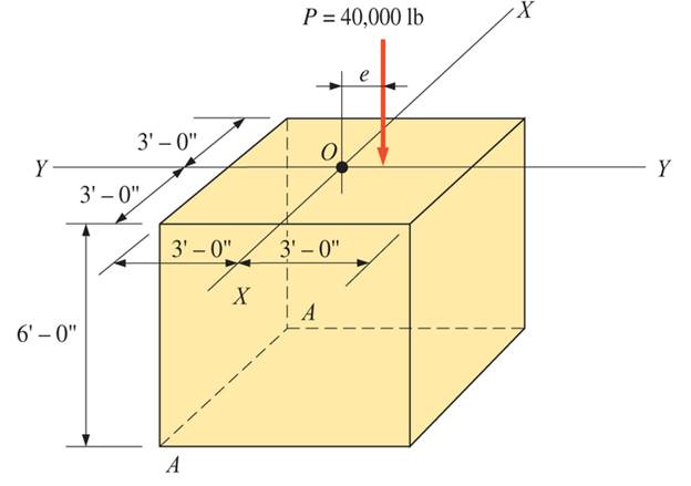
A concrete pedestal is in the shape of a cube and is 6 ft on each side. The pedestal supports a superimposed load of 40,000 lb located on the Y-Y axis, as shown. Calculate the maximum eccentricity e for zero tension at the base of the pedestal. Include the weight of the pedestal using a concrete unit weight of 150 pcf.

Expert Solution & Answer
Want to see the full answer?
Check out a sample textbook solution
Students have asked these similar questions
The rigid bar BC is supported by the steel rod AC of cross-sectional area 0.31 in2. Find the vertical displacement (in inches and
absolute value) of point Coaused by the 2888-lb load if x = 8.7 ft and 8 = 46.5-. Use E = 29159 ksi for steel. Note: Round off the
final answer to four decimal places.
Rigid
B
P
PROBLEM 3. The aluminum rod has a
solid circular cross-section and supports
the loading shown. Drawing the normal
force diagram and keeping the weight
minimum, determine the diameter of the
rod at each segment AB, BC, CD and DE.
Compare the weight of the rod if the
magnesium alloy AZ91D was used as the
rod material.
8 kN
E
4 kN
6 kN
2 kN
4 m
-2 m-
2m-2 m-
The armor shown supports loads of 3 KN. The horizontal elements are 713cm long each. Determine the axial force on element FE; Use the section method to determine the axial force in the FE element and check your result with the nodal or joint method.
INFO: Y= 100 cm
Chapter 17 Solutions
Applied Statics and Strength of Materials (6th Edition)
Ch. 17 - Prob. 17.1PCh. 17 - A horizontal 30-ft simple span beam is supported...Ch. 17 - A 1-in.-by-4-in, steel bar is subjected to the...Ch. 17 - A W410100 structural steel wide-flange section is...Ch. 17 - A W1272 structural steel wide-flange section is...Ch. 17 - A solid steel shaft 3 in. in diameter and 4 ft...Ch. 17 - A short compression member is subjected to a...Ch. 17 - With reference to Problem 17.7, calculate the...Ch. 17 - A section of a 51-mm-diameter standard-weight...Ch. 17 - For the pipe of Problem 17.9, compute the maximum...
Ch. 17 - A concrete pedestal is in the shape of a cube and...Ch. 17 - 17.12 For the pedestal of Problem 17.11, assume...Ch. 17 - 17.13 Rework Problem 17.11, but assume that the...Ch. 17 - A 12-in-square concrete pedestal is subjected to a...Ch. 17 - 17.15 A short compression member is subjected to a...Ch. 17 - A rectangular concrete footing, 4 ft by 8 ft in...Ch. 17 - The bending and shear stresses developed at a...Ch. 17 - Stresses developed at a point in a machine part...Ch. 17 - Calculate the principal stresses at points A and B...Ch. 17 - 17.20 Rework Problem 17.19 using P = 8000 lb and...Ch. 17 - 17.21 A 1-in.-square steel bar is subjected to an...Ch. 17 - 17.22 A bar having a cross-sectional area of 6...Ch. 17 - Rework Problem 17.22, changing the load to a...Ch. 17 - Solve Problem l7.17 using Mohr’s circle.Ch. 17 - For the elements shown in Problem 17.18, use...Ch. 17 - Solve Problem 17.19 using Mohr’s circle.Ch. 17 - In Problem 17.19, change the load to 8000 lb and...Ch. 17 - For the following computer problems, any...Ch. 17 - For the following computer problems, any...Ch. 17 - For the following computer problems, any...Ch. 17 - For the following computer problems, any...Ch. 17 - A 4-in.-by-8-in. (S4S) Douglas fir timber beam is...Ch. 17 - A horizontal flexural member (a girt) in the wall...Ch. 17 - A simply supported W1850 structural steel...Ch. 17 - A steel link in a machine is designed to avoid...Ch. 17 - 17.36 An 8-in-square (S4S) vertical timber post is...Ch. 17 - A short 3-in.-square steel bar with a...Ch. 17 - A timber member 150 mm by 250 mm (S4S) is loaded...Ch. 17 - A concrete wall 8 ft high and 3 ft thick is...Ch. 17 - 17.40 A short compression member is subjected to a...Ch. 17 - 17.41 Calculate the maximum eccentric load that...Ch. 17 - A short compression member is subjected to two...Ch. 17 - 17.43 Calculate the force P that may be applied to...Ch. 17 - 17.44 A load of 1000 lb is supported on a...Ch. 17 - 17.45 A short compression member is subjected to...Ch. 17 - 17.46 A structural steel wide-flange section is...Ch. 17 - 17.47 A cast-iron frame for a piece of industrial...Ch. 17 - 17.48 The assembly shown is used in a machine. It...Ch. 17 - 17.49 A 50-mm-diameter solid steel shaft is...Ch. 17 - An element of a machine member is subjected to the...Ch. 17 - 17.51 A short-span cantilever built-up beam has...Ch. 17 - Solve Problem 17.50 using Mohr’s circle.Ch. 17 - 17.53 A cantilever beam is subjected to an...Ch. 17 - A 6-in.-diameter solid shaft is subjected to a...Ch. 17 - Rework parts (b) and (c) of Example 17.7 using...
Knowledge Booster


Learn more about
Need a deep-dive on the concept behind this application? Look no further. Learn more about this topic, mechanical-engineering and related others by exploring similar questions and additional content below.Similar questions
- A circular steel bar of length 10 m having 0.5 N/m of specific weight is hanging on its self weight. The diameter of the bar is 0.5 m. Calculate the elongation in bar due to its self weight.arrow_forward8. Plot a graph of the internal axial forces in segments AB, BC and CD vs. distance measured from A for the system shown below; 47 kip 82 kip 47 kip 8 ft. B 2 in. 5 ft- C 28.5 kip D 28.5 kip 41- 45 kiparrow_forwardPROBLEM 3. The aluminum rod has a solid circular cross-section and supports the loading shown. Drawing the nomal force diagram and keeping the weight minimum, detemine the diameter of the rod at each segment AB, BC, CD and DE. Compare the weight of the rod if the magnesium alloy AZ91D was used as the rod material. 8 kN 4 kN 6 kN 2 kN -4 m -2 m- -2 marrow_forward
- The boom in the figure below (Figure 1) weighs 3000 NN and is attached to a frictionless pivot at its lower end. It is not uniform; the distance of its center of gravity from the pivot is 40%% of its length. Make a free-body diagram of the boom. The boom attaches to the building at dot A. The center of gravity of the boom is indicated by dot B. The guy wire attaches to the boom and holds the load at dot C. Find the tension in the guy wire. Find the horizontal component of the force exerted on the boom at its lower end. Find the vertical component of the force exerted on the boom at its lower endarrow_forwardThe tires of the 4,240 lb sedan are 7.5 in. wide. Each tire contacts the ground over a distance of l = 4.3 in. as measured along the vehicle's length. Calculate the compressive stress between each tire and the road. The locations of the vehicle's mass center and the wheelbase dimensions are shown. 40 in.' 100 in. Calculate the compressive stress between the front tire and the road: (Express your answer using three significant figures.) OF psi Calculate the compressive stress between the rear tire and the road: (Express your answer using two significant figures.) |psi OR =arrow_forwardWhat is the value of P of the vertical force required to lift the wheelbarrow free of the ground at point B? The combined weight of the wheelbarrow and its load is 202 lb with center of gravity at G is given in figure below.arrow_forward
- Examine the rod below. It is fixed into a wall at the left hand end. From the wall to point B is 200mm. BC is 200mm long and CD is 200mm long. (Centreline to centreline distances). Point A lies on the positive Y-axis on a cross section halfway along BC. Three forces are applied at D. P=221.6, your individual load, is parallel to the z-axis. 400N is parallel to the y-axis and 200N is parallel to the x axis. The rod is a tube with an 80mm outer diameter and a wall thickness of 5mm. What is the net sigma (s) and the net tau (t) at Point A? Show all your working. Make sure you clearly indicate the direction/sign of each stress you calculate.arrow_forward4- For the structure shown, calculate bearing reactions. 10 1200 Ib 2000 lb 100 lb/ftarrow_forwardA straight girder of uniform section and length L rests on supports at the ends, and is propped up by a third support in the middle. The weight of the girder and its load is w per unit length. If the central support does not yield, prove that it takes a load equal to (5/8)wL. ANSWER: 1.80cm and 2.48cm Please show solution to the answer.arrow_forward
- 1. A rod of length 1.50 m and diameter 0.12 m is mounted in a rigid wall. A vertical bar of length 0.5 m is attached to the free end from the centroid of the rod. The rigid bar is loaded with a horizontal force of P= 50 kN at its free end. A torque T=-8 kN.m is also applied to the free end, as shown in Fig. 1. An axial test of the material of the rod shows that it has the following mechanical properties: E=210 GPa, o = 280 MPa, and v 3 (The origin of the coordinate system is at the wall). (a) Draw a free-body diagram of the structure in Fig. 1. Note FBD means no attachment to the structure) (b) Use strength of materials to compute the stress components, and then (c) Write the stress tensor, as a matrix at a point on the bottom of the rod. (d) Determine the principal stresses at the same point as in (c). (e) Determine (i) the strain energy density (U.) of the rod; and (ii) the total strain energy U stored in the rod (requires volume of the rod). (f) Determine the factor of safety if the…arrow_forwardAxial loads are applied with rigid bearing plates to the solid cylindrical rods shown. If F1 = 30 kips, F2 = 10 kips, F3 = 26 kips, and F4 = 37 kips, determine the absolute value of the axial load in rod (2).arrow_forwardThe triangular block below is subjected to the Loads P=1200 lb and 400 lb. If AB=8 in, and BC is 6in., resolve each load into components normal and tangential to AC.arrow_forward
arrow_back_ios
SEE MORE QUESTIONS
arrow_forward_ios
Recommended textbooks for you
 Elements Of ElectromagneticsMechanical EngineeringISBN:9780190698614Author:Sadiku, Matthew N. O.Publisher:Oxford University Press
 Mechanics of Materials (10th Edition)Mechanical EngineeringISBN:9780134319650Author:Russell C. HibbelerPublisher:PEARSON
 Thermodynamics: An Engineering ApproachMechanical EngineeringISBN:9781259822674Author:Yunus A. Cengel Dr., Michael A. BolesPublisher:McGraw-Hill Education
 Control Systems EngineeringMechanical EngineeringISBN:9781118170519Author:Norman S. NisePublisher:WILEY
 Mechanics of Materials (MindTap Course List)Mechanical EngineeringISBN:9781337093347Author:Barry J. Goodno, James M. GerePublisher:Cengage Learning
 Engineering Mechanics: StaticsMechanical EngineeringISBN:9781118807330Author:James L. Meriam, L. G. Kraige, J. N. BoltonPublisher:WILEY
Elements Of Electromagnetics
Mechanical Engineering
ISBN:9780190698614
Author:Sadiku, Matthew N. O.
Publisher:Oxford University Press
Mechanics of Materials (10th Edition)
Mechanical Engineering
ISBN:9780134319650
Author:Russell C. Hibbeler
Publisher:PEARSON
Thermodynamics: An Engineering Approach
Mechanical Engineering
ISBN:9781259822674
Author:Yunus A. Cengel Dr., Michael A. Boles
Publisher:McGraw-Hill Education
Control Systems Engineering
Mechanical Engineering
ISBN:9781118170519
Author:Norman S. Nise
Publisher:WILEY
Mechanics of Materials (MindTap Course List)
Mechanical Engineering
ISBN:9781337093347
Author:Barry J. Goodno, James M. Gere
Publisher:Cengage Learning
Engineering Mechanics: Statics
Mechanical Engineering
ISBN:9781118807330
Author:James L. Meriam, L. G. Kraige, J. N. Bolton
Publisher:WILEY
EVERYTHING on Axial Loading Normal Stress in 10 MINUTES - Mechanics of Materials; Author: Less Boring Lectures;https://www.youtube.com/watch?v=jQ-fNqZWrNg;License: Standard YouTube License, CC-BY