
Statics and Mechanics of Materials (5th Edition)
5th Edition
ISBN: 9780134382593
Author: Russell C. Hibbeler
Publisher: PEARSON
expand_more
expand_more
format_list_bulleted
Videos
Textbook Question
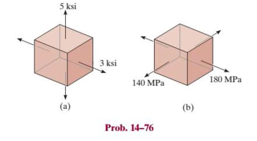
Chapter 14.5, Problem 76P
Draw the three Mohr’s circles that describe each of the following states of stress.
Expert Solution & Answer
Want to see the full answer?
Check out a sample textbook solution
Students have asked these similar questions
Draw the three Mohr’s circles that describe the following state of stress.
Draw Mohr’s circle that describes each of the following states of stress.
Use Mohr's circle to find the stress on the slope indicated by the dotted line when the stress state is as follows.
Chapter 14 Solutions
Statics and Mechanics of Materials (5th Edition)
Ch. 14.3 - In each ease, the state of stress x, y, xy...Ch. 14.3 - Given the state of stress shown on the element,...Ch. 14.3 - Determine the normal stress and shear stress...Ch. 14.3 - Prob. 2FPCh. 14.3 - Determine the equivalent state of stress on an...Ch. 14.3 - Prob. 4FPCh. 14.3 - The beam is subjected to the load at its end....Ch. 14.3 - Prob. 6FPCh. 14.3 - Prove that the sum of the normal stresses x+y=x+y...Ch. 14.3 - Determine the stress components acting on the...
Ch. 14.3 - Determine the stress components acting on the...Ch. 14.3 - Determine the normal stress and shear stress...Ch. 14.3 - Determine the normal stress and shear stress...Ch. 14.3 - Prob. 6PCh. 14.3 - Prob. 7PCh. 14.3 - Determine the stress components acting on the...Ch. 14.3 - Determine the stress components acting on the...Ch. 14.3 - Determine the stress components acting on the...Ch. 14.3 - Determine the equivalent state of stress on an...Ch. 14.3 - Prob. 12PCh. 14.3 - Determine the stress components acting on the...Ch. 14.3 - Determine (a) the principal stresses and (b) the...Ch. 14.3 - Prob. 15PCh. 14.3 - Prob. 16PCh. 14.3 - Prob. 17PCh. 14.3 - Prob. 18PCh. 14.3 - Prob. 19PCh. 14.3 - Prob. 20PCh. 14.3 - Prob. 21PCh. 14.3 - The state of stress at a point in a member is...Ch. 14.3 - The wood beam is subjected to a load of 12 kN. If...Ch. 14.3 - Prob. 24PCh. 14.3 - The internal loadings at a section of the beam are...Ch. 14.3 - The internal loadings at a section of the beam are...Ch. 14.3 - Prob. 27PCh. 14.3 - Prob. 28PCh. 14.3 - The beam has a rectangular cross section and is...Ch. 14.3 - A paper tube is formed by rolling a cardboard...Ch. 14.3 - Prob. 31PCh. 14.3 - The 2-in.-diameter drive shaft AB on the...Ch. 14.3 - Determine the principal stresses in the...Ch. 14.3 - The internal loadings at a cross section through...Ch. 14.3 - The internal loadings at a cross section through...Ch. 14.3 - Prob. 36PCh. 14.3 - The steel pipe has an inner diameter of 2.75 in....Ch. 14.3 - Prob. 38PCh. 14.3 - The wide-flange beam is subjected to the 50-kN...Ch. 14.3 - Prob. 40PCh. 14.3 - The box beam is subjected to the 26-kN force that...Ch. 14.3 - The box beam is subjected to the 26-kN force that...Ch. 14.4 - Use Mohrs circle to determine the normal stress...Ch. 14.4 - Prob. 8FPCh. 14.4 - Prob. 9FPCh. 14.4 - Prob. 10FPCh. 14.4 - Prob. 11FPCh. 14.4 - Prob. 12FPCh. 14.4 - Solve Prob. 142 using Mohrs circle. 14-2.Determine...Ch. 14.4 - Solve Prob. 143 using Mohrs circle. 143.Determine...Ch. 14.4 - Determine the stress components acting on the...Ch. 14.4 - Solve Prob. 1410 using Mohrs circle. 149.Determine...Ch. 14.4 - Solve Prob. 1415 using Mohrs circle. 1415.The...Ch. 14.4 - Solve Prob. 1416 using Mohrs circle....Ch. 14.4 - Prob. 49PCh. 14.4 - Determine (a) the principal stresses and (b) the...Ch. 14.4 - Determine (a) the principal stresses and (b) the...Ch. 14.4 - Determine the equivalent state of stress if an...Ch. 14.4 - Draw Mohrs circle that describes each of the...Ch. 14.4 - Draw Mohrs circle that describes each of the...Ch. 14.4 - Determine (a) the principal stresses and (b) the...Ch. 14.4 - Determine (a) the principal stress and (b) the...Ch. 14.4 - Determine (a) the principal stresses and (b) the...Ch. 14.4 - Determine (a) the principal stresses and (b) the...Ch. 14.4 - Determine (a) the principal stresses and (b) the...Ch. 14.4 - Prob. 60PCh. 14.4 - The grains of wood in the board make an angle of...Ch. 14.4 - The post is fixed supported at its base and a...Ch. 14.4 - Determine the principal stresses, the maximum...Ch. 14.4 - The thin-walled pipe has an inner diameter of 0.5...Ch. 14.4 - The frame supports the triangular distributed load...Ch. 14.4 - The frame supports the triangular distributed load...Ch. 14.4 - Prob. 67PCh. 14.4 - The pedal crank for a bicycle has the cross...Ch. 14.4 - A spherical pressure vessel has an inner radius of...Ch. 14.4 - The cylindrical pressure vessel has an inner...Ch. 14.4 - Prob. 71PCh. 14.4 - Determine the principal stress at point D, which...Ch. 14.4 - If the box wrench is subjected to the 50 lb force,...Ch. 14.4 - If the box wrench is subjected to the 50-lb force,...Ch. 14.4 - Prob. 75PCh. 14.5 - Draw the three Mohrs circles that describe each of...Ch. 14.5 - Draw the three Mohrs circles that describe the...Ch. 14.5 - Draw the three Mohrs circles that describe the...Ch. 14.5 - Determine the principal stresses and the absolute...Ch. 14.5 - Prob. 80PCh. 14.5 - Prob. 81PCh. 14.5 - Prob. 82PCh. 14.8 - Prove that the sum of the normal strains in...Ch. 14.8 - The state of strain at the point on the arm has...Ch. 14.8 - The state of strain at the point on the pin leaf...Ch. 14.8 - The state of strain at the point on the pin leaf...Ch. 14.8 - Prob. 88PCh. 14.8 - The state of strain at a point on the bracket has...Ch. 14.8 - Prob. 90PCh. 14.8 - Prob. 91PCh. 14.8 - Prob. 92PCh. 14.8 - Prob. 93PCh. 14.8 - Prob. 94PCh. 14.8 - Prob. 95PCh. 14.8 - Prob. 96PCh. 14.8 - Prob. 97PCh. 14.8 - The state of strain on the element has components...Ch. 14.8 - Solve Prob. 1486 using Mohrs circle. 1486.The...Ch. 14.8 - Solve Prob. 1487 using Mohrs circle. 1486.The...Ch. 14.8 - Solve Prob. 1488 using Mohrs circle. 1488.The...Ch. 14.8 - Solve Prob. 1491 using Mohrs circle. 1491.The...Ch. 14.8 - Solve Prob. 1490 using Mohrs circle. 1489.The...Ch. 14.11 - The strain at point A on the bracket has...Ch. 14.11 - The strain at point A on a beam has components...Ch. 14.11 - The strain at point A on the pressure-vessel wall...Ch. 14.11 - The 45 strain rosette is mounted on the surface of...Ch. 14.11 - Prob. 109PCh. 14.11 - Use Hookes law, Eq. 1432, to develop the strain...Ch. 14.11 - Prob. 111PCh. 14.11 - A rod has a radius of 10 mm. If it is subjected to...Ch. 14.11 - The polyvinyl chloride bar is subjected to an...Ch. 14.11 - The polyvinyl chloride bar is subjected to an...Ch. 14.11 - The spherical pressure vessel has an inner...Ch. 14.11 - Determine the bulk modulus for each of the...Ch. 14.11 - The strain gage is placed on the surface of the...Ch. 14.11 - The principal strains at a point on the aluminum...Ch. 14.11 - Prob. 119PCh. 14.11 - Prob. 120PCh. 14.11 - The cube of aluminum is subjected to the three...Ch. 14.11 - The principal strains at a point on the aluminum...Ch. 14.11 - A uniform edge load of 500 lb/in. and 350 lb/in....Ch. 14.11 - Prob. 124PCh. 14 - The steel pipe has an inner diameter of 2.75 in....Ch. 14 - Prob. 2RPCh. 14 - Prob. 3RPCh. 14 - The crane is used to support the 350-lb load....Ch. 14 - In the case of plane stress, where the in-plane...Ch. 14 - The plate is made of material having a modulus of...Ch. 14 - If the material is graphite for which Eg = 800 ksi...Ch. 14 - A single strain gage, placed in the vertical plane...Ch. 14 - The 60 strain rosette is mounted on a beam. The...
Knowledge Booster


Learn more about
Need a deep-dive on the concept behind this application? Look no further. Learn more about this topic, mechanical-engineering and related others by exploring similar questions and additional content below.Similar questions
- Q-1) For the given state of stress, (a) draw Mohr's circle for this state of stress and show all values on it (b) determine the principal planes and the principal stresses, (c) determine the normal and shearing stresses after the element shown has been rotated through 25° clockwise, (d) determine the normal and shearing stresses after the element shown has been rotated through 10° counterclockwise. (e) Show the Gmax, min. Op, Os, Tmaxs o' values on an appropriate plane stress sketch. NOTE: The problem will be solved by only MOHR CIRCLE Method and all stresses and angles will be computed and indicated on Mohr Circle. All steps of solution will be displayed. Analytical solution will not be graded. 90 MPa + 30 MPa 60 MPaarrow_forwardDetermine the resulting maximum value of the normal stress. Specify the orientation of the plane on which these maximum values occur. **The answer is tensile stress is 0 ksi at 90 degrees. **The answer is compressive stress is 7 ksi at 0 degrees. Can you explain how that is? This was my thought process: I know that tensile would be zero because the force P is actually going inwards and not outwards. I know that means that there would be a compressive force. I am confused on the angles, how is a tensile force going 90 degress if there technically is no force in the tensile direction. And how is there a compressive force at 90 degrees if there is a stress? thank you!arrow_forwardThe element in the image has a horizontal force of 20 N and a vertical force of 25 N. The element was made of a 25.4 mm diameter steel bar. Determine:to. The four states of stress from the farthest place of the forces and obtain the critical point.b. For the critical point, construct the Mohr circle.C. Obtain the maximum principal and normal shear stresses for the critical point.d. The angles at which the maximum normal and shear stresses occur.and. Draw the rotated tension state for the angles obtained and with the corresponding tensions.arrow_forward
- The 20 mm diameter rod is subjected to the loads shown. (a) Determine the state of stress at point A and show the results on a differential element located at this point. (b) Using Mohr's circle, determine the maximum normal stress and the maximum in-plane shearing stress at point A and show the associated stress states on appropriately oriented elements, for each case. 75 mm 375 N B 200 mm 450 Narrow_forwardIllistrate Mohr's circle for the given plane stress state. Including the coordinates of the points, show the points with the faces of the figure, the center of the circle and the magnitude of the radius. 7. 3kPa 5kPa 1kPaarrow_forwardThe state of stress at a point on an element of material is shown. Let sigmaX= 49.0 ksi, sigmaY= 17.0 ksi, and Txy= 11.0 ksi. Use this information to represent the principle state of stress and maximum in plane shear stress. Plot the mohr circle and state sigmaX' and sigmaY' and Tx'y' with unit. Also draw the state of stress on the rotated element.arrow_forward
- Determine the equivalent state of stress if an element is oriented 60° clockwise from the element shown.arrow_forwardSolve parts (a) to (c) using transformation equations only (not Mohr's circle), and show the complete state of stress with the appropriate stress element properly oriented relative to the given xy coordinate system. Given the state of plane stress shown, (a) determine the state of stress for an element oriented 20° clockwise relative to the given xy coordinate system. (b) determine the state of stress for the element containing the principal stresses. (c) determine the state of stress for the element containing the maximum in- plane shear stresses. (d) determine the state of stress for the element containing the maximum shear stresses. (e) draw Mohr's circle indicating the states of stress and angular orientation found in parts (a) to (c). - 8 MPa 40 MPa 12 MPa xarrow_forwardProblem 1: A state of plane stress at a point on the surface of a structure consists of the following stress components: Ox = 25 ksi, oy = 12 ksi, and Txy = 10 ksi. Note that the stress components act in the directions shown on the element below. Ox Txy 12 ksi 5 25 ksi 10 ksi (a) Draw a complete Mohr's circle for this stress state. Clearly label the X and Y faces, the center C, and the radius R. (b) Using Mohr's circle, determine the principal stresses, the maximum in-plane shear stress, and the normal stress that acts on the maximum shear stress plane. Label all of these quantities on the circle. (c) Calculate the orientation of the principal planes and the planes of maximum shear stress. Label all of these quantities on the circle. (d) Show all stresses from part (b) on properly oriented stress element(s). Be sure to include all stress components acting on the elements(s).arrow_forward
- For the loading shown on the L-shaped part, determine the state of stress at points a, b, and c. Write each state of 12 in. stress in the form of a tensor, observing the r-y-z coor- dinate system shown, and sketch the stresses acting on a differential element at each point. 12 kip 1.8 in. 6 in. 12 kip 0. in. 1.0 in. 1.0 in.arrow_forwardThe main stresses and directions and the maximum shear stress;The tension state for a 30° clockwise rotation.Mohr's Circle.arrow_forwardThe main stress, the maximum shear stress, and the dead angle are obtained when the stress is given as shown in the picture below.Draw Mohr's circle.arrow_forward
arrow_back_ios
SEE MORE QUESTIONS
arrow_forward_ios
Recommended textbooks for you
 Elements Of ElectromagneticsMechanical EngineeringISBN:9780190698614Author:Sadiku, Matthew N. O.Publisher:Oxford University Press
 Mechanics of Materials (10th Edition)Mechanical EngineeringISBN:9780134319650Author:Russell C. HibbelerPublisher:PEARSON
 Thermodynamics: An Engineering ApproachMechanical EngineeringISBN:9781259822674Author:Yunus A. Cengel Dr., Michael A. BolesPublisher:McGraw-Hill Education
 Control Systems EngineeringMechanical EngineeringISBN:9781118170519Author:Norman S. NisePublisher:WILEY
 Mechanics of Materials (MindTap Course List)Mechanical EngineeringISBN:9781337093347Author:Barry J. Goodno, James M. GerePublisher:Cengage Learning
 Engineering Mechanics: StaticsMechanical EngineeringISBN:9781118807330Author:James L. Meriam, L. G. Kraige, J. N. BoltonPublisher:WILEY
Elements Of Electromagnetics
Mechanical Engineering
ISBN:9780190698614
Author:Sadiku, Matthew N. O.
Publisher:Oxford University Press
Mechanics of Materials (10th Edition)
Mechanical Engineering
ISBN:9780134319650
Author:Russell C. Hibbeler
Publisher:PEARSON
Thermodynamics: An Engineering Approach
Mechanical Engineering
ISBN:9781259822674
Author:Yunus A. Cengel Dr., Michael A. Boles
Publisher:McGraw-Hill Education
Control Systems Engineering
Mechanical Engineering
ISBN:9781118170519
Author:Norman S. Nise
Publisher:WILEY
Mechanics of Materials (MindTap Course List)
Mechanical Engineering
ISBN:9781337093347
Author:Barry J. Goodno, James M. Gere
Publisher:Cengage Learning
Engineering Mechanics: Statics
Mechanical Engineering
ISBN:9781118807330
Author:James L. Meriam, L. G. Kraige, J. N. Bolton
Publisher:WILEY
An Introduction to Stress and Strain; Author: The Efficient Engineer;https://www.youtube.com/watch?v=aQf6Q8t1FQE;License: Standard YouTube License, CC-BY