
Videos
The crossover circuit in Fig. 14.109 is a high-pass filter that is connected to a tweeter. Determine the transfer function H(ω) = Vo(ω)/Vi(ω).
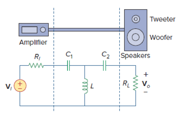
Figure 14.109
Find the transfer function
Answer to Problem 97P
The transfer function
Explanation of Solution
Given data:
Refer to Figure 14.109 in the textbook.
Formula used:
Write a general expression to calculate the impedance of resistor in s-domain.
Here,
Write a general expression to calculate the impedance of an inductor in s-domain.
Here,
Write a general expression to calculate the impedance of a capacitor in s-domain.
Here,
Write the general expression to calculate the transfer function of the system
Here,
Calculation:
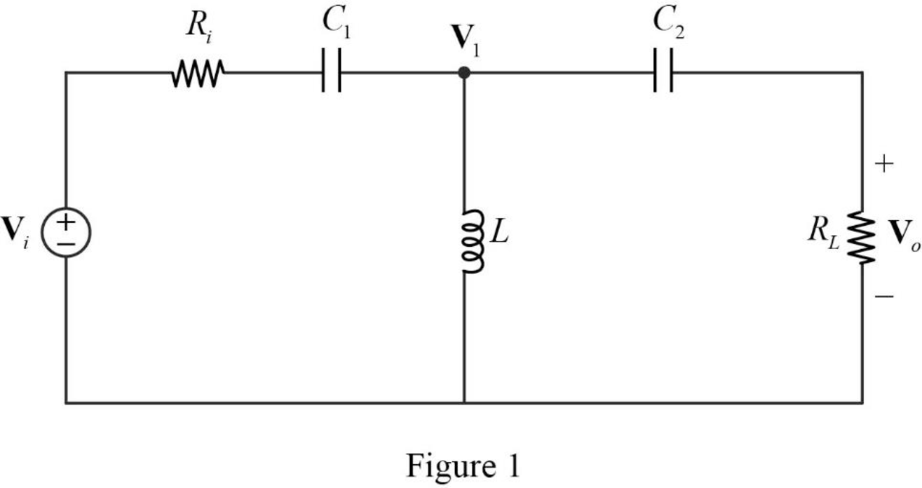
The given circuit is redrawn as Figure 1.
Use equation (1) to find
Use equation (1) to find
Use equation (2) to find
Use equation (3) to find
Use equation (3) to find
The s-domain circuit of the Figure 1 is drawn as Figure 2.
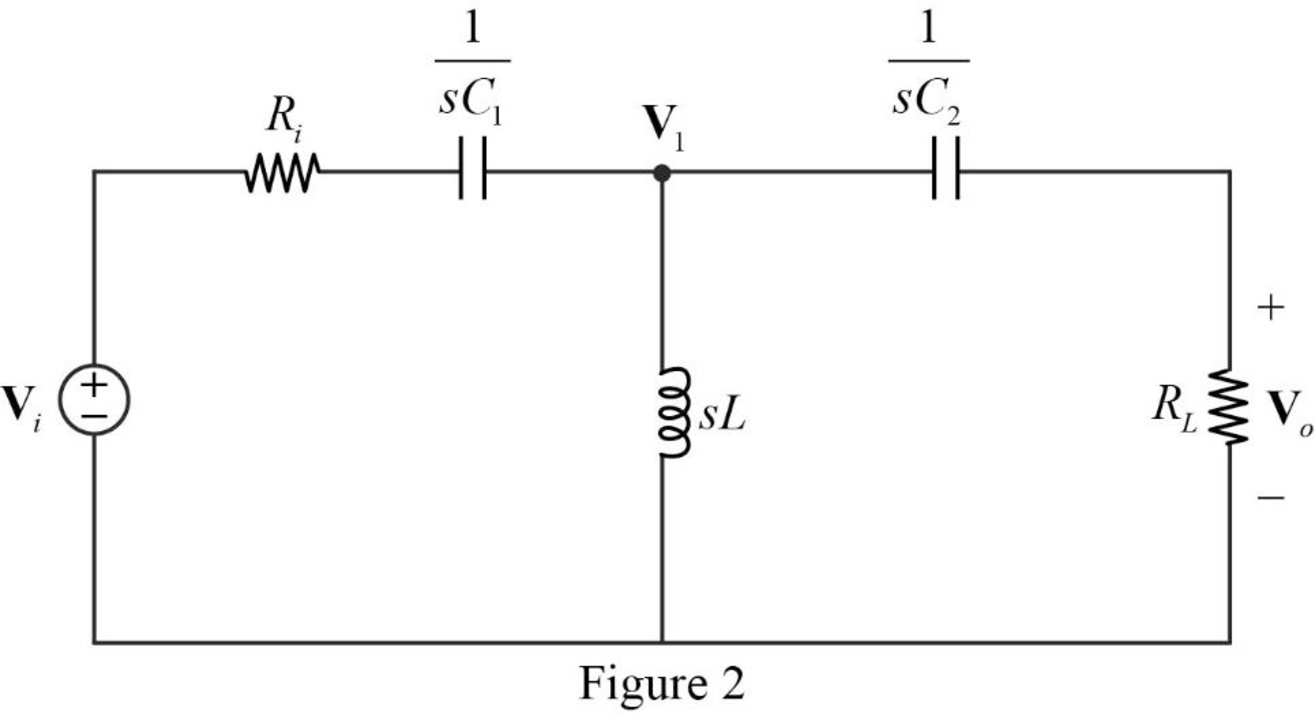
Refer to Figure 2, the series connected impedances
Therefore, the equivalent impedance is calculated as follows.
Simplify the above equation to find
The reduced circuit of the Figure 2 is drawn as Figure 3.
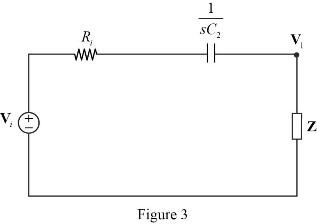
Apply voltage division rule on Figure 3 to find
Apply voltage division rule on Figure 2 to find
Substitute
Rearrange the above equation to find
Substitute
Simplify the above equation to find
Simplify the above equation to find
Substitute
Simplify the above equation to find
From equation (5), the equation (4) becomes,
Conclusion:
Thus, the transfer function
Want to see more full solutions like this?
Chapter 14 Solutions
Fundamentals of Electric Circuits


- Ineed an answer with details as soon as possible please Q/ Using capacitors and resistors, If you know that the capacitance of the capacitor you should use is 100nF A - Design (low-pass filters) with cutoff Frequency =115HZ. B - Design (High-pass filters) with cutoff Frequency = 215HZarrow_forwardThe OLTF of a system is 30,000 G(s) = = s4+67s³+1017s²+8637s+13725 What is the phase crossover frequency? What is the gain crossover frequency? What is the gain margin? What is the phase margin? dB degrees. rad/s rad/sarrow_forwardElectrical Engineering Find the transfer function H(f) of the following circuit and sketch the Bode magnitude and phase plots: 5002 + Vout Vin 480 µFarrow_forward
- Electrical Engineering Design a low-pass, high-pass, and band-pass filter based on the following schematic selecting your own values for components. Analyse the circuits in frequency iden- tifying center and cut-off frequencies. Build and verify the operation of the circuit based on the designs. V_L+ VC+ V_Lref V Cref VR+ 10.0mH 5.0µF Vin R1 5V Vout 500HZ 10.00 V Rrefarrow_forwardFor the circuit shown in Fig. 14.80, next page: (a) Calculate the resonant frequency , the quality factor Q, and the bandwidth B. (b) What value of capacitance must be connected in series with the 20-F capacitor in order to double the bandwidth? 5 mH m 20 μF 25 ΚΩ Figure 14.80 For Prob. 14.41. 10 mHarrow_forwardQuestion 4 (a) Draw the approximate gain Bode plot (no need for log-linear graph paper) for the following transfer function. Provide suitable numerical information on this plot. 100 G(s) = 4s2 +12s +100arrow_forward
- A coil with resistance of 10 ohms and an inductance of 15 mH is connected in series to the parallel combination of a 20 ohms resistor and a 100 uF capacitor. The circuit is energized by a 120 Vac, variable frequency supply. Derive the formula for resonant frequency and use it to find the resonant frequency.arrow_forwardChapter 14, Problem 61. Find the transfer function for each of the active filters in Fig. 14.90. + ō 0+10 Vi R ww 〒3 (a) с R (b) 1+ O + Vo + Voarrow_forwardFind the transfer function Vo/Vs of the circuit in Fig. 14.86. Show that the circuit is a low-pass filter.arrow_forward
- В Vin -w Vo Figure 14.91 (Exercise 14.40) Figure 14.91 shows the cascaded RC sections that form the feedback network for the RC phase-shift oscillator. Show that the feedback ratio is Vin с www.m R с с HE R³ (R³ -- 5RX²) + j(X² – 6R²Xc)arrow_forwardFor the circuits in Fig. 14.81, find the resonant frequency , the quality factor Q, and the bandwidth B. 202 www 622 www (a) ΤΗ 0.4 F Figure 14.81 For Prob. 14.42. m 20 mH 2kQ2 (b) 3 µF :6 μFarrow_forwardQ.1) Draw Bode Plot of the following Open Loop Transfer Function: (1+ 10 H(s) = 40- s(1+50)(1+20oarrow_forward
 Introductory Circuit Analysis (13th Edition)Electrical EngineeringISBN:9780133923605Author:Robert L. BoylestadPublisher:PEARSON
 Delmar's Standard Textbook Of ElectricityElectrical EngineeringISBN:9781337900348Author:Stephen L. HermanPublisher:Cengage Learning
 Programmable Logic ControllersElectrical EngineeringISBN:9780073373843Author:Frank D. PetruzellaPublisher:McGraw-Hill Education
 Fundamentals of Electric CircuitsElectrical EngineeringISBN:9780078028229Author:Charles K Alexander, Matthew SadikuPublisher:McGraw-Hill Education
 Electric Circuits. (11th Edition)Electrical EngineeringISBN:9780134746968Author:James W. Nilsson, Susan RiedelPublisher:PEARSON
 Engineering ElectromagneticsElectrical EngineeringISBN:9780078028151Author:Hayt, William H. (william Hart), Jr, BUCK, John A.Publisher:Mcgraw-hill Education,