
University Physics Volume 2
18th Edition
ISBN: 9781938168161
Author: OpenStax
Publisher: OpenStax
expand_more
expand_more
format_list_bulleted
Videos
Textbook Question
thumb_up100%
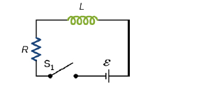
Chapter 14, Problem 55P
How long after switch S1 is thrown does it take the current in the circuit shown to reach half its maximum value? Express your answer in terms of the time constant of the circuit.
Expert Solution & Answer
Want to see the full answer?
Check out a sample textbook solution
Students have asked these similar questions
The capacitor in the circuit shown below is initially uncharged. The switch is closed at t = 0 s. AV battery = 30 V, C = 3.0 F, and R = 2.0
2. At sometime after the switch is closed, the current in the circuit is measured to be 9.3 A. What is the charge on the capacitor at this
time, in Coulomb?
Your answer needs to have 2 significant figures, including the negative sign in your answer if needed. Do not include the positive sign if the
answer is positive. No unit is needed in your answer, it is already given in the question statement.
A battery with Ɛ= 6.00 V supplies current to the circuit shown in Figure. Given, R1 = 1Ω, R2 = 2Ω and R3 = 3Ω.
Calculate the current I in R1, R2 and R3: [10 marks]
when the switch S is open as shown in the figure
When the switch is closed in position a
When the switch is closed in position b
The capacitor in the circuit shown below is initially uncharged. The switch is closed at t = 0 s. ΔVbattery = 30 V, C = 3.0 F, and R = 2.0 Ω. At sometime after the switch is closed, the current in the circuit is measured to be 6.1 A. What is the charge on the capacitor at this time, in Coulomb?
Chapter 14 Solutions
University Physics Volume 2
Ch. 14 - Check Your Understanding. A current...Ch. 14 - Check Your Understanding. Current flows through...Ch. 14 - Check Your Understanding. A changing current...Ch. 14 - Check Your Understanding (a) Calculate the...Ch. 14 - Check Your Understanding (a) What is the magnetic...Ch. 14 - Check Your Understanding How much energy is stored...Ch. 14 - Check Your Understanding Verify that RC and L/R...Ch. 14 - Check Your Understanding (a) If the current in the...Ch. 14 - Check Your Understanding For the circuit of in...Ch. 14 - Check Your Understanding The angular frequency of...
Ch. 14 - Check Your Understanding In an RLC circuit, L =...Ch. 14 - Show that N m /l and el(dl/dt), which are both...Ch. 14 - A 10-H inductor carries a current of 20 A....Ch. 14 - The ignition circuit of an automobile is powered...Ch. 14 - When the current through a large inductor is...Ch. 14 - Does self-inductance depend on the value of the...Ch. 14 - Would the self-inductance of a 1.0 m long, tightly...Ch. 14 - Discuss how you might determine the-inductance per...Ch. 14 - The self-inductance of a coil is zero if there is...Ch. 14 - How does the self- inductance per unit length near...Ch. 14 - Solve that I I 2 /2 has units of energy.Ch. 14 - Use Lenz’s law to explain why the initial current...Ch. 14 - When the current in the RL circuit of Figure...Ch. 14 - Does the time required for the current in an RL...Ch. 14 - An inductor is connected across the terminals of a...Ch. 14 - At what time is the voltage across the inductor of...Ch. 14 - In the simple RL circuit of Figure 14.12(b), can...Ch. 14 - If emf of the battery of Figure 14.12(b) is...Ch. 14 - A steady current flows through a circuit with a...Ch. 14 - Describe how the currents through R1and R2, shown...Ch. 14 - Discuss possible practical applications of RL...Ch. 14 - Do Kirchhoff’s rules apply to circuits that...Ch. 14 - Can a circuit e1eent have both capacitance and...Ch. 14 - In an LC circuit, what determines the frequency...Ch. 14 - When a wire is connected between the two ends of a...Ch. 14 - Describe what effect the resistance of the...Ch. 14 - Suppose you wanted to design an LC circuit with a...Ch. 14 - A radio receiver uses an RLC circuit to pick out...Ch. 14 - When the current in one coi1 changes at a rate of...Ch. 14 - An emf of 9.7 × 10⁻³ V is induced in a coil while...Ch. 14 - Two coils close to each other have a mutual...Ch. 14 - A coil of 40 turns is wrapped around a long...Ch. 14 - A 600-turn solenoid is 0.55 m long and 4.2 cm in...Ch. 14 - A toroidal coil has a mean radius of 16 cm and a...Ch. 14 - A solenoid of N1turns has length l1and radius R1,...Ch. 14 - An emf of 0.40 V is induced across a coil when the...Ch. 14 - The current shown in part (a) below is increasing,...Ch. 14 - What is the rate at which the current though a...Ch. 14 - When a camera uses a flash, a fully charged...Ch. 14 - A coil with a self-inductance of 2.0 H carries a...Ch. 14 - A solenoid 50 cm long is wound with 500 turns of...Ch. 14 - A coil with a self-inductance of 3.0 H carries a...Ch. 14 - The current I(t) through a 5.0-mH inductor varies...Ch. 14 - A long, cylindrical solenoid with 100 turns per...Ch. 14 - Suppose that a rectangular toroid has 2000...Ch. 14 - What is the self-inductance per meter of a coaxial...Ch. 14 - At the instant a current of 0.20 A is flowing...Ch. 14 - Suppose that a rectangular toroid has 2000...Ch. 14 - Solenoid A is tightly wound while solenoid B has...Ch. 14 - A 10-H inductor carries a current of 20 A. How...Ch. 14 - A coil with a self-inductance of 3.0 H and a...Ch. 14 - A current of 1.2 A is flowing in a coaxial cable...Ch. 14 - In Figure 14.12, =12V , L = 20 mH, and R=5.0....Ch. 14 - For the circuit shown below, =20V , L = 4.0 mH,...Ch. 14 - The current in the RL circuit shown here increases...Ch. 14 - How long after switch S1 is thrown does it take...Ch. 14 - Examine the circuit shown below in part (a)....Ch. 14 - The current in the RL circuit shown below reaches...Ch. 14 - Consider the circuit shown below. Find l1, l2and...Ch. 14 - For the circuit shown below, =50V , R1= 10 , and...Ch. 14 - For the circuit shown below, find the current...Ch. 14 - Show that for the circuit shown below, the initial...Ch. 14 - A 5000-pF capacitor is charged to 100 V and then...Ch. 14 - The self-inductance and capacitance of an LC...Ch. 14 - What is the self-inductance of an LC circuit that...Ch. 14 - In an oscillating LC circuit the maximum charge on...Ch. 14 - The self-inductance and capacitance of an...Ch. 14 - In an oscillating LC circuit, the maximum charge...Ch. 14 - In the circuit shown below, S1is opened and S2is...Ch. 14 - An LC circuit in an AM tuner (in a car stereo)...Ch. 14 - In an oscillating RLC circuit, R=5.0 ,. L=5.0mH ,...Ch. 14 - In an oscillating RLC circuit with L = 10 mH, C =...Ch. 14 - What resistance R must be connected in series with...Ch. 14 - Show that the self-inductance per unit length of...Ch. 14 - Two long, parallel wires cy equal currents in...Ch. 14 - A small, rectangular single loop of wire with...Ch. 14 - Suppose that a cylindrical solenoid is wrapped...Ch. 14 - A solenoid with 4 x 10⁷turns/m has an iron core...Ch. 14 - A rectangular toroid with inner radius R1= 7.0cm,...Ch. 14 - The switch S of the circuit shown below is closed...Ch. 14 - In an oscillating RLC circuit, R = 7.0 L. = 10...Ch. 14 - A 25.0-H inductor has 100 A of current turned off...Ch. 14 - A coaxial cable has an inner conductor of radius...Ch. 14 - In a damped oscillating circuit the energy is...Ch. 14 - The switch in the circuit shown below is closed at...Ch. 14 - A square loop of side 2 cm is placed 1 cm from a...Ch. 14 - A rectangular copper ring, of mass 100 g and...
Additional Science Textbook Solutions
Find more solutions based on key concepts
Amount of energy coal use accounts for.
Glencoe Physical Science 2012 Student Edition (Glencoe Science) (McGraw-Hill Education)
24.41 When a 360-nF air capacitor (1 nF = 10?9F) is connected to a power supply, the energy stored in the capac...
University Physics with Modern Physics (14th Edition)
Whether this is stable equilibrium for object or not.
Physics (5th Edition)
A friend says, “It makes no sense that Anna could turn on lights in her hands simultaneously in her frame but t...
Modern Physics
18. 0.15 m3 = _________cm3
Applied Physics (11th Edition)
A hockey puck moving at 32 m/s slams through a wall of snow 35 cm thick. It emerges moving at 18 m/s. Assuming ...
Essential University Physics (3rd Edition)
Knowledge Booster


Learn more about
Need a deep-dive on the concept behind this application? Look no further. Learn more about this topic, physics and related others by exploring similar questions and additional content below.Similar questions
- For the circuit shown below, Ɛ = 32 V, R, = 27 N, R, = 54 N, R3 = 81 N, and L = 4.0 mH. Find the values of I, and I, (in A) at the following times. R1 R3 1/2 R2 (a) immediately after switch S is closed I, = A I2 A (b) a long time after S is closed I, A I2 A (c) immediately after S is reopened (Assume the circuit has reached a steady state before S is reopened.) I = A I2 A = (d) a long time after S is reopened A I, = A 0000arrow_forwardin the circuit shown in the figure, the S switch is closed at t=0 and the capasitors, which are completely empty, begin to fill. Here E=30V, C=3 uF and R=40 ohm. A) what is the time constant of the circuit, T, in the units of microseconds? B)when t=T, what is the total charge, in units of microcoulomb?arrow_forwardThe capacitor in the figure is initially uncharged and the switch is at position c and not connected to either side of the circuit. At t = 0, the switch is flipped to position a for 20 ms, then flipped to position b for 10 ms, flipped back to position a for 20 ms again, and finally flipped to position c. Find the graph of the current through and the voltage across the capacitor as functions of time.arrow_forward
- A battery with E = 7.80 V and no internal resistance supplies current to the circuit shown in the figure below. When the double-throw switch S is open as shown in the figure, the current in the battery is 1.00 mA. When the switch is closed in position a, the current in the battery is 1.16 mA. When the switch is closed in position b, the current in the battery is 1.80 mA. R R2 R2 S Rs (a) Find the resistance R,. kΩ (b) Find the resistance R. kΩ (c) Find the resistance R2arrow_forwardApply the loop rule to loop 2 (the smaller loop on the right). Sum the voltage changes across each circuit element around this loop going in the direction of the arrow. Remember that the current meter is ideal. Express the voltage drops in terms of VbVbV_b, I2I2I_2, I3I3I_3, the given resistances, and any other given quantities.arrow_forwardIn the circuit of the figure below, the switch S has been open for a long time. It is then suddenly closed. Take = 10.0 V, R₁ = 41.0 km2, R₂ = 170 kn, and C = 12.0 μF. E R₁ www i (a) Determine the time constant before the switch is closed. 2.532 S I = & (b) Determine the time constant after the switch is closed. 2.04 S 1 R₁ (c) Let the switch be closed at t = 0. Determine the current in the switch as a function of time. (Assume I is in A and t is in s. Do not enter units in your expression. Use the following as necessary: t.) + www R₂ C R2 Xarrow_forward
- In the circuit of the figure below, the switch S has been open for a long time. It is then suddenly closed. Take E = 10.0 V, R, = 57.0 kN, R, = 105 kN, and C = 13.5 µF. R1 + S R2 (a) Determine the time constant before the switch is closed. (b) Determine the time constant after the switch is closed. (c) Let the switch be closed at t = 0. Determine the current in the switch as a function of time. (Assume I is in A and is in s. Do not enter units in your expression. Use the following as necessary: t.) I =arrow_forwardA battery with Ɛ = 4.80 V and no internal resistance supplies current to the circuit shown in the figure below. When the double-throw switch S is open as shown in the figure, the current in the battery is 1.00 mA. When the switch is closed in position a, the current in the battery is 1.12 mA. When the switch is closed in position b, the current in the battery is 1.82 mA. R1 R2 R2 + R3 (a) Find the resistance R,. (b) Find the resistance R,. (c) Find the resistance R2.arrow_forwardAt time t=0, the switch in the circuit shown in the figure is closed. After a sufficiently long time, steady currents I1 ,I2 and I3 flow through resistors R1 ,R2 and R3 , respectively. Determine these three currents.arrow_forward
- I am trying to find the true expressions about this circuit but I keep getting the wrong answer, What are the right equations. The answers I currently have so far are: A, B, Darrow_forwardChapter 30, Problem 054 In the figure, ε = 118 V, R₁ = 14.9 №, R₂ = 21.3 N, R3 = 35.8 №, and L= 1.90 H. Immediately after switch S is closed, what are (a) i₁ and (b) i₂? (Let currents in the indicated directions have positive values and currents in the opposite directions have negative values.) A long time later, what are (c) ₁ and (d) i2? The switch is then reopened. Just then, what are (e) ₁ and (f) i₂? A long time later, what are (g) ₁ and (h) i₂? www R₁ R$ R₂ Larrow_forwardConsider the circuit shown in the figure. A) Let the equivalent resistance of the circuit when the switch is open be Req,open, and the equivalent resistance when the switch is closed be Req,closed. Find the difference (in Ω) between the two equivalent resistances, Req,open-Req,closed. B) When the switch S is closed, the equivalent resistance drops to 54.0% of the original value. Determine the value of R (in Ω). C) What would the voltage (in V) between points a and b have to be for 160 W to be delivered to the circuit when the switch is closed? Assume that R has the value found in part (b).arrow_forward
arrow_back_ios
SEE MORE QUESTIONS
arrow_forward_ios
Recommended textbooks for you
 College PhysicsPhysicsISBN:9781305952300Author:Raymond A. Serway, Chris VuillePublisher:Cengage Learning
 University Physics (14th Edition)PhysicsISBN:9780133969290Author:Hugh D. Young, Roger A. FreedmanPublisher:PEARSON
 Introduction To Quantum MechanicsPhysicsISBN:9781107189638Author:Griffiths, David J., Schroeter, Darrell F.Publisher:Cambridge University Press
 Physics for Scientists and EngineersPhysicsISBN:9781337553278Author:Raymond A. Serway, John W. JewettPublisher:Cengage Learning
 Lecture- Tutorials for Introductory AstronomyPhysicsISBN:9780321820464Author:Edward E. Prather, Tim P. Slater, Jeff P. Adams, Gina BrissendenPublisher:Addison-Wesley
 College Physics: A Strategic Approach (4th Editio...PhysicsISBN:9780134609034Author:Randall D. Knight (Professor Emeritus), Brian Jones, Stuart FieldPublisher:PEARSON
College Physics
Physics
ISBN:9781305952300
Author:Raymond A. Serway, Chris Vuille
Publisher:Cengage Learning
University Physics (14th Edition)
Physics
ISBN:9780133969290
Author:Hugh D. Young, Roger A. Freedman
Publisher:PEARSON
Introduction To Quantum Mechanics
Physics
ISBN:9781107189638
Author:Griffiths, David J., Schroeter, Darrell F.
Publisher:Cambridge University Press
Physics for Scientists and Engineers
Physics
ISBN:9781337553278
Author:Raymond A. Serway, John W. Jewett
Publisher:Cengage Learning
Lecture- Tutorials for Introductory Astronomy
Physics
ISBN:9780321820464
Author:Edward E. Prather, Tim P. Slater, Jeff P. Adams, Gina Brissenden
Publisher:Addison-Wesley
College Physics: A Strategic Approach (4th Editio...
Physics
ISBN:9780134609034
Author:Randall D. Knight (Professor Emeritus), Brian Jones, Stuart Field
Publisher:PEARSON
What is Electromagnetic Induction? | Faraday's Laws and Lenz Law | iKen | iKen Edu | iKen App; Author: Iken Edu;https://www.youtube.com/watch?v=3HyORmBip-w;License: Standard YouTube License, CC-BY