
Concept explainers
Videos
For the pump and piping system of Prob. 14-35E, plot the required pump head
The plot between the available head and the capacity of the pump.
Answer to Problem 36EP
The plot between the available head and the capacity of the pump is 
Explanation of Solution
Given information:
The shutoff head is
Write the expression for the required head using the energy balance equation.
Here, the initial pressure is
Write the expression for the roughness factor.
Here, the diameter of the pipe is
Write the expression for the minor losses.
Here, the minor loss coefficient at pipe entrance is
Write the expression for the frictional loss head.
Here, the friction factor is
Write the expression for the available head.
Here, the shutoff head is
Write the expression for the capacity.
Substitute
Write the expression for the Reynolds number.
Here, the density of the water is
Write the expression for the friction factor using the Colebrook equation.
Calculation:
Refer to table A-3E Properties of saturated water to obtain the density of water as
Substitute
Substitute
Substitute
Substitute
Since, the required head is equal to the available head that is
Substitute
Substitute
Substitute
Substitute
Substitute
Substitute
The different values of the capacity and the available head is shown in the below Table.
| S.No. | Capacity | Available head |
| 1 | ||
| 2 | ||
| 3 | ||
| 4 |
Draw the plot between the available head and the capacity of the pump for different values along with the required head.
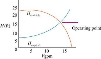
Figure-(1)
Conclusion:
The plot between the available head and the capacity of the pump is 
Want to see more full solutions like this?
Chapter 14 Solutions
Fluid Mechanics: Fundamentals and Applications


- A pump delivers water from a tank (A)X water surface elevation-110m) to tank B (water surface elevation= 170m). The suction pipe is 45m long and 35cm in diameter the delivered pipe is 950m long 25cm in diameter. Loss head due to friction hf1 = 5m and h2 3m If the piping are from pipe(1)= steel sheet metal pipe(2)= stainless – steel Calculate the following i) ii) The discharge in the pipeline The power delivered by the pump.arrow_forwardProb-2 HL=8.5 m Compute discharge pressure of Pump: Elevation=50m Psuction =-40Kpag Pdischarge = Elevation=80m H₂Oarrow_forward2. For a piping system as shown in the figure, determine the distribution of the water flow Qi and the piezometric height H at the junction. The powerof the pump is YQH, = 20 kW. constant, equal to inputAssume the friction factor is constant el 30 m Pipe L (m) D (m) f ΣΚ el 15 m 50 0.15 0.02 2 el 10 m [2] 100 0.10 0.015 1 300 0.10 0.025 1 P [1] B [3] 123arrow_forward
- The head-discharge characteristic relationship of a pump is given by:H = 40 - 200*Q^2, where H is the total head generated by the pump in meters and Q is the discharge in m^3/s. The pump lifts water through a pipe 0.3 meter diameter over a distance of 1000 meters against a static lift of 25 meters. Find the operating/ duty point (H and Q) if the friction coefficient of the pipe 'f ' is 0.03.arrow_forwardG1/ In the fig.shown, the Flow rate Pipe (A) is equal ( QA = 25 Lit15), the diameter is equal ( DA = 75 mm, D, = De = Dc =30mm), and the velocity in Pipe (D) is equal (Uo=5 m/s), the relation between flow rate in in 6o mm, Pipe (B) and pipe (c) GB =3 Qc. Find the Value of '. Re, Qc, Qo. 2- UA, UB, Uc: Pe = 30 mm water Pc = 30mm imput QA = 25 2i+/sec OA= 75 mm = 6o mm input = A outPut = B, C, D accumulation = o.arrow_forwardProblem Set No. 1 1. A 200 kg chunk of lead falls from a height of 30 m and smashes into a rigid concrete floor. Calculate the increase in the internal energy AU (MJ), assuming that no energy is transferred as heat from the lead. 2. Assess the capabilities of a hydroelectric power plant from the following field data: Estimated water flow rate, 40 m³/s River inlet at 1 atm, 10 °C Discharge at 1 atm, 10.2 °C, 200 m below the intake 3. How much energy transfer as heat is required to evaporate completely 1 kg of nitrogen for a constant pressure process, with T = 89.5 K? 4. One kg of CO₂ is heated in a 0.5 m³ vessel from -18 °C to 93 °C. Determine the initial and final states, and the amount of energy transfer as heat to the CO2. 5. The condensate pump on the Navaho power plant raises the water pressure from 3.5 in of mercury to 390 psia at a flow rate of 5,100 gal/min. If the pump isentropic efficiency is 0.8, calculate the power required in hp. 6. Calculate the thermal efficiency of a…arrow_forward
- 1 QUESTION 1 Consider a desired pump operating condition which adds 35 psi at a flowrate of 500 gpm to water (p= 62 11m/ft²³) Ignore any changes in Kinetic or potential energy and Tassume isothermal flow C.e. internal energy is constant, this is the normal assumption we make when analyzing fluid flows in piping systems). Apply the energy balance only across the pump with full energy Balance and simlifying to solve for the pump, Starting head symbolically. Then begin careful of units, Solve for pump head in feet. GIVEN: 35psi 500 gpm p=62 1bm/3 XA. 10.5 A B. 100.8 ft C. 50.1 ft D. 80.7f 35 500 62 (32.2) + 2(32.2) 35 + 500arrow_forwardA (300mm) diameter of pipe, if the discharge (90 L/sec), nozzle diameter (75mm) and pipe length from (1 to 2) was (100m) Determine the length of pipe from (2 to 3), and the pressure at point (2). (e-0.026mm, v1.13" 10 m?/sec). Fig(1) 6m 23m Fig.(1) Nozzlearrow_forwardSUPPLEMENTARY QUESTION The figure shows two reservoirs connected by a pipe. The discharge rate in the pipe is known to be equal to SN/100 (m2/s) (where SN is the sum of your student number). Calculate the height of the second reservoir (H2), and the pressure head, velocity head and elevation head at point 3 (mid-point of the pipe). HI 300 m H2 datum A = SN/1000 L = 100 x SN (m) D 0.3 m Please solve these question my sn number 31arrow_forward
- The total head of fan is 200m and has a static pressure of 201mm of water gage. What is the velocity of air flowing if density is 1.16kg/m3. ANSWER: 22.9arrow_forwardTwo reservoirs, A and B having elevations 250 m and 100 m, respectively, are connected by a 250-mm diameter pipe, with a length of 250 m. A turbine is installed between the two reservoirs. The flow of water in the pipe is 140 L/s. Use C = 120. Use the equation of Hazen - Williams for head loss as, h₂ 10.67LQ1.85 C1.85 D4.87 Calculate the head loss. Determine the head extracted by the turbine. Find the power generated by the turbine.arrow_forwardThe three-arm lawn sprinkler receives 20°C water through the centre at 2.7 m3/hr. If collar friction is negligible, what is the steady rotation rate in (w = ? rad/s) ? Assume e = 15°. V cos e %3D %3D Note: w = R V d =7 mm R = 15 cmarrow_forward
 Elements Of ElectromagneticsMechanical EngineeringISBN:9780190698614Author:Sadiku, Matthew N. O.Publisher:Oxford University Press
 Mechanics of Materials (10th Edition)Mechanical EngineeringISBN:9780134319650Author:Russell C. HibbelerPublisher:PEARSON
 Thermodynamics: An Engineering ApproachMechanical EngineeringISBN:9781259822674Author:Yunus A. Cengel Dr., Michael A. BolesPublisher:McGraw-Hill Education
 Control Systems EngineeringMechanical EngineeringISBN:9781118170519Author:Norman S. NisePublisher:WILEY
 Mechanics of Materials (MindTap Course List)Mechanical EngineeringISBN:9781337093347Author:Barry J. Goodno, James M. GerePublisher:Cengage Learning
 Engineering Mechanics: StaticsMechanical EngineeringISBN:9781118807330Author:James L. Meriam, L. G. Kraige, J. N. BoltonPublisher:WILEY