
Concept explainers
Videos
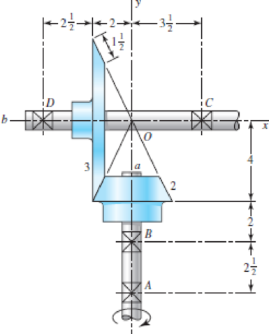
The figure shows a 16T 20° straight bevel pinion driving a 32T gear, and the location of the bearing centerlines. Pinion shaft a receives 2.5 hp at 240 rev/min. Determine the bearing reactions at A and B if A is to take both radial and thrust loads.
Problem 13–43
Dimensions in inches.
The bearing reaction at
The bearing reaction at
Answer to Problem 43P
The bearing reaction at
The bearing reaction at
Explanation of Solution
The figure below shows the forces acting at the bevel gear and pinion assembly.
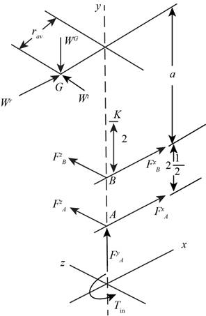
Figure-(1)
Write the expression for the input torque.
Here, the power is
Write the expression for the pitch angle for gear 2.
Here, the distance between the gear 3 and y axis is
Write the expression fort the pitch radius at the mid-point of the bevel gear.
Here, the lateral side of the gear 3 is
Write the expression for the tangential load.
Write the expression for the pitch angle for gear 3.
Write the expression for the radial load.
Here, the pressure angle is
Write the expression for the axial load.
Write the expression of the load in vector form.
Calculate the value of
Write the expression for the position vector of
Here, the distance between the points
Write the expression for the position vector of
Write the expression for the force on the bearing
Here, the force on bearing
Write the expression for the moment about gear 4 in vector form.
Write the expression for the force equilibrium for the set of bearings.
Substitute
Conclusion:
Substitute
Substitute
Substitute
Substitute
Substitute
Substitute
Substitute
Substitute
Substitute
Substitute
Compare the
Compare the
Compare the
Substitute
Thus, the bearing reaction at
Substitute
Thus, the bearing reaction at
Want to see more full solutions like this?
Chapter 13 Solutions
Shigley's Mechanical Engineering Design (McGraw-Hill Series in Mechanical Engineering)


- 13-55 Gear 2, in the figure, has 16 teeth, a 20° transverse pressure angle, a 15° helix angle, and a module of 4 mm. Gear 2 drives the idler on shaft b, which has 36 teeth. The driven gear on shaft c has 28 teeth. If the driver rotates at 1600 rev/min and transmits 6 kW, find the radial and thrust load on each shaft. LH 90° Problem 13-55 RH RHarrow_forward13-32 The 247 6-pitch 20° pinion 2 shown in the figure rotates clockwise at 1000 rev/min and is driven at a power of 25 hp. Gears 4, 5, and 6 have 24, 36, and 144 teeth, respectively. What torque can arm 3 deliver to its output shaft? Draw free-body diagrams of the arm and of each gear and show all forces that act upon them.arrow_forwardThe figure shows a 10 diametral pitch 18-tooth 20° straight bevel pinion driving a 38-tooth gear. The transmitted load is 35 lbf. Find the bearing reactions at D on the output shaft if it is to take both radial and thrust loads. Problem 13-44 Dimensions in inches. 3 0 72 이 012441100 2 The bearing reactions at D on the output shaft due to radial load FD, radialis 57.987 lbf and due to thrust load FD, thrust is 4.803 lbf. €arrow_forward
- A Coniflex, straight-tooth bevel gearset is supported on shafts with centerlines intersecting at a 90° angle. The gear is straddle mounted between closely positioned bearings, and the pinion overhangs its support bearing. The 15-tooth pinion rotates at 900 rpm, driving the 60-tooth gear, which has a di- ametral pitch of 6, pressure angle of 20°, and face width of 1.25 inches. The material for both gears is through-hardened Grade I steel with a hardness of BHN 300 (see Figure). It is desired to have a reliability of 90 percent, a design life of 10° cy- cles, and a governing safety factor of 2.5. Estimate the maximum horsepower that can be transmitted by this gear re- ducer while meeting all of the design specifications given.arrow_forwardThe reducer input shaft shown in the figure is taperedIt transmits moment with the help of a gear wheel.On the spindle, Fa = 552 N, Fr = 457 N, Ft = 1960 Nfrom gear forces and belt mechanismincoming Fk = 2600 N radial force impact. The shaft rotates with n = 1090 rpm.Accept the shaft diameter in the A bearing as dA = 35 mm.Fixed ball bearing for Lh = 13500 hselectarrow_forward187 13-40 The figure shows a pair of shaft-mounted spur gears having a diametral pitch of 5 teeth/in with an 18-tooth 20° pinion driving a 45-tooth gear. The power input is 32-hp at 1800 rev/min. Find the direction and magnitude of the forces acting on bearings A, B, C, and D. 13-41 The figure shows the electric-motor frame dimensions for a 30-hp 900 rev/min motor. The frame is bolted to its support using four -in bolts spaced 11 in apart in the view shown and 14 in apart when viewed from the end of the motor. A 4 diametral pitch 20° spur pinion having 20 teeth and a face width of 2 in is keved to and fluch with 3 in 3 in Problem 13-40arrow_forward
- The figure shows a pair of shaft-mounted spur gears having a diametral pitch of 5 teeth/in with an 18-tooth 20° pinion driving a 45-tooth gear. The power input is 28-hp at 1700 rev/min. Find the magnitude of the force acting on bearing D. 3 2 3 in 3 in The magnitude of the force acting on bearing Dis lbf.arrow_forwardThe figure shows a pair of shaft-mounted spur gears having a module of 5 mm with an 18-tooth 20° pressure angle pinion driving a 45-tooth gear. The power input is 24 kW at 1800 rev/min counterclockwise into the pinion. Find the direction and magnitude of the forces acting on the shafts a and b. SOLUTION:arrow_forwardThe 24T 6-pitch 20° pinion 2 shown in the figure rotates clockwise at 900 rev/min and is driven at a power of 28 hp. Gears 4, 5, and 6 have 24, 36, and 144 teeth, respectively. NOTE: This is a multi-part question. Once an answer is submitted, you will be unable to return to this part. Fixed What torque can arm 3 deliver to its output shaft? The torque that arm 3 delivers to its output shaft is lbf-in.arrow_forward
- A steel spur pinion has 16 teeth cut on the 20° full-depth system with a module of 8 mm and a face width of 90 mm. The pinion rotates at 150 rev/min and transmits 4 kW to the mating steel gear. This pinion is to mesh with a steel gear with a gear ratio of 4:1. The Brinell hardness of the teeth is 200, and the tangential load transmitted by the gears is 4 kN. If the contact fatigue strength of the steel can be estimated from the AGMA formula of Sc= 2.22 HB + 200 MPa, estimate the factor of safety of the drive based on a surface fatigue failure. The factor of safety of the drive is 3.086arrow_forwardThe reducer input shaft shown in the figure is tapered It transmits moment with the help of a gear wheel. On the spindle, Fa = 552 N, Fr = 457 N, Ft = 1960 N from gear forces and belt mechanism incoming Fk = 2600 N radial force impact . The shaft rotates with n = 1090 rpm. Accept the shaft diameter in the A bearing as dA = 35 mm. Fixed ball suitable for Lh = 13500 h select bearing.arrow_forward14-4 A steel spur pinion has 15 teeth cut on the 20° full-depth system with a module of 5 mm and a face width of 60 mm. The pinion rotates at 200 rev/min and transmits 5 kW to the mating steel gear. What is the resulting bending stress?arrow_forward
 Elements Of ElectromagneticsMechanical EngineeringISBN:9780190698614Author:Sadiku, Matthew N. O.Publisher:Oxford University Press
 Mechanics of Materials (10th Edition)Mechanical EngineeringISBN:9780134319650Author:Russell C. HibbelerPublisher:PEARSON
 Thermodynamics: An Engineering ApproachMechanical EngineeringISBN:9781259822674Author:Yunus A. Cengel Dr., Michael A. BolesPublisher:McGraw-Hill Education
 Control Systems EngineeringMechanical EngineeringISBN:9781118170519Author:Norman S. NisePublisher:WILEY
 Mechanics of Materials (MindTap Course List)Mechanical EngineeringISBN:9781337093347Author:Barry J. Goodno, James M. GerePublisher:Cengage Learning
 Engineering Mechanics: StaticsMechanical EngineeringISBN:9781118807330Author:James L. Meriam, L. G. Kraige, J. N. BoltonPublisher:WILEY